Wenzhou Prance Hydraulic Equipment Co., Ltd

Long Hoses in Hydraulic Motor Drives: Compliance and Response Lag
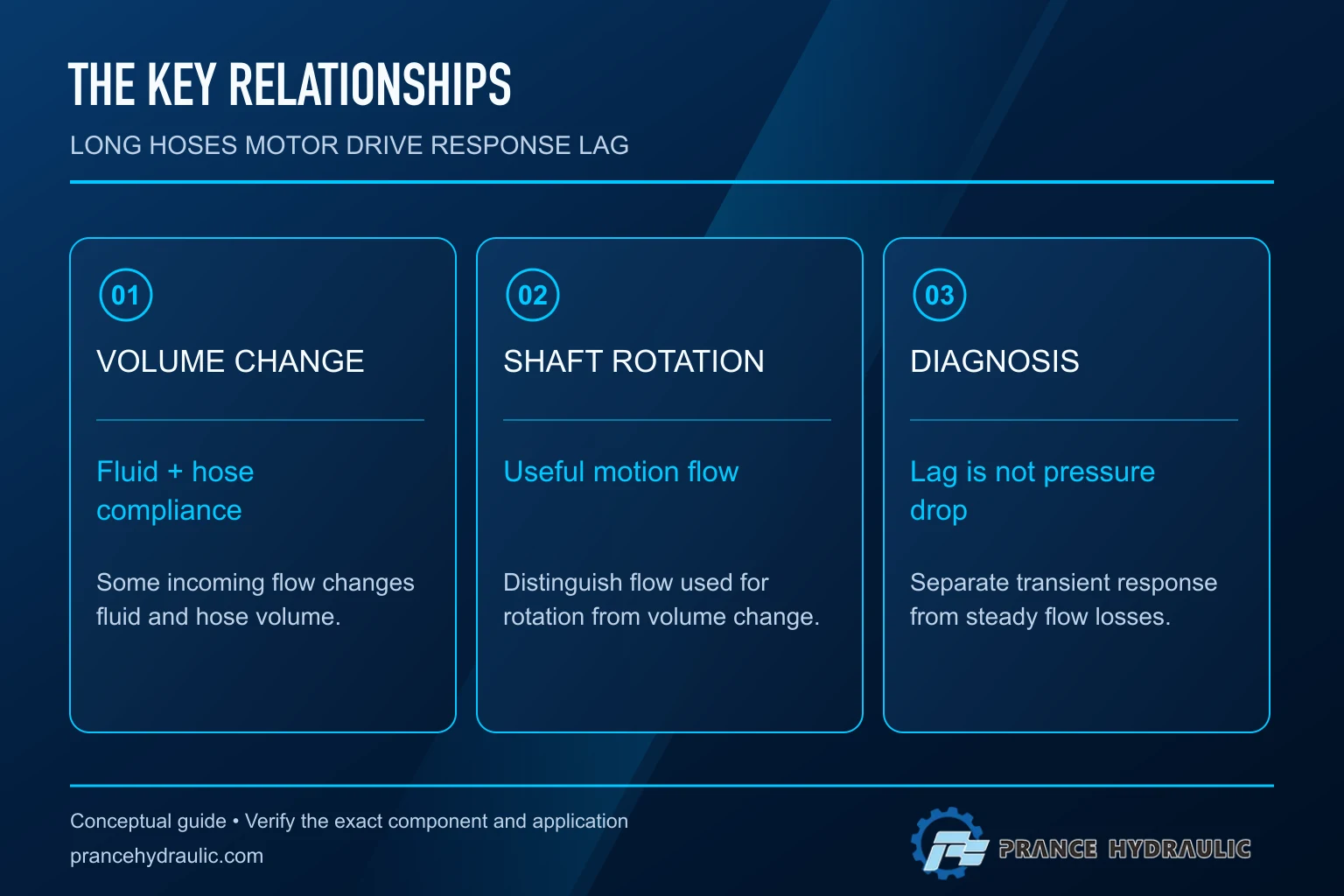
Long hoses in a hydraulic motor drive can delay response because part of the incoming flow changes the pressure and stored volume of the circuit before it becomes useful shaft motion. The effect depends on enclosed oil volume, oil compressibility, hose-wall expansion, trapped air, load and the controller. Hydraulic motor hose compliance is therefore different from steady pressure drop. A circuit can have acceptable running losses yet respond slowly during a start, reversal or load change.
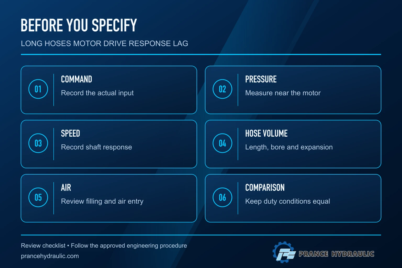
Start the investigation by measuring command, pressure near the motor and shaft speed on a common time base. Do not immediately increase controller gain or enlarge the valve. Those changes may conceal the cause, increase overshoot or create an unstable drive. This guide explains the transient volume balance and how to distinguish compliance from restriction, insufficient supply and mechanical delay.
What changes when the hose becomes longer
A longer line usually encloses more oil when the internal diameter stays the same. More oil volume requires more delivered fluid to produce the same pressure change. The hose wall also expands under pressure, adding another form of volume storage. Fittings, manifolds and connected chambers contribute to the actual enclosed volume, so hose length alone is not a complete model.
Diameter produces a tradeoff. A larger bore can reduce frictional pressure loss, but it also increases enclosed volume at the same length. That does not make large hoses inherently wrong. It means diameter should be selected for the whole operating duty, including pressure loss, velocity, transient response and installation requirements. The answer is not simply to choose the smallest hose for stiffness or the largest hose for low loss.
Not every section is active in the same way during every motion. A directional valve may isolate one section or connect it to return; a check valve may create a trapped volume; and an over-running motor may place different demands on the opposite line. Use the actual circuit and valve states to identify the volume that is being pressurized in the event under investigation.
Compressibility and hose expansion share the incoming flow
A useful conceptual balance is that incoming flow supports motor displacement flow, internal leakage and the change in stored volume. In a simple lumped model, the storage component can be written as Qstorage = Ceff × dp/dt, where Ceff is effective volume compliance. This is a teaching relationship, not a complete model of a long transmission line or a specific motor installation.
NPTEL’s hydraulic-fluid lesson defines bulk modulus through pressure and relative volume change. For fluid compression alone, compliance is approximately V/Beff, where V is enclosed fluid volume and Beff is an effective bulk modulus. Hose expansion and other elastic elements add compliance. Air can greatly change the effective response, especially as operating pressure changes. Treat a nominal oil property as an input assumption, not a substitute for the behavior of the assembled hose, fluid and circuit.
If available inflow is initially consumed by storage and leakage, the motor cannot immediately reach the speed predicted by a steady-state flow calculation. As pressure builds sufficiently to support load torque, shaft acceleration begins or increases. Load inertia then introduces another delay. The observed start response is the combined result of hydraulic storage, torque generation, inertia and control behavior.
A numerical example with explicit assumptions
Assume an illustrative enclosed oil volume of 4 L, an assumed effective bulk modulus of 1,000 MPa, and a pressure increase of 10 MPa. The fluid-only volume change is approximately V × change in pressure / bulk modulus: 4 × 10 / 1,000 = 0.04 L. If a constant 2 L/min were available only for compression, filling that change would take about 1.2 seconds.
This is not a prediction for a Prance motor or a real hose. The modulus and volume are hypothetical, hose-wall expansion is omitted, flow is assumed constant, leakage is omitted and the motor is assumed not to move during the calculation. Real available storage flow can change continuously as the valve opens, supply pressure changes and the load begins moving. The example shows why a seemingly small compressed volume can matter when the excess flow is small.
If the enclosed volume doubles under the same simplified assumptions, the compressed volume and calculated charging time double. If effective stiffness falls because the assembly is more compliant, more storage volume is required. These proportional relationships help compare proposed changes, but commissioning measurements are needed before assigning an actual response time.
Separate compliance from steady pressure drop
Pressure drop is associated with flow through restrictions and friction. Compliance describes volume change with pressure. Both can be present in the same hose and can influence one another through the operating point. A hose that causes a large running loss may leave insufficient differential pressure at the motor; a compliant line may delay the rise even when its eventual running loss is modest.
Measure on both sides of the suspected section where the approved test arrangement permits it. Pump pressure alone cannot reveal pressure at the motor during the transient. A pressure reading upstream of a valve may include losses and blocked-volume effects that are absent at the motor inlet. Record return-side pressure as well because motor torque depends on the appropriate differential, not a single gauge value.
Avoid diagnosing the drive from a slow gauge with unknown damping. Sensor bandwidth, sampling rate, filtering and timestamp alignment can change the apparent order of events. Establish whether an observed delay exceeds the measurement uncertainty. Instrumentation must meet pressure and fluid requirements and must not create a restrictive drain or unsafe hose connection.
A diagnostic comparison table
| Observed pattern | Possible explanation | Useful comparison | Avoid assuming |
|---|---|---|---|
| Command changes before local pressure responds | Control, valve or storage delay | Command versus local pressure trace | The motor itself is defective |
| Local pressure rises before shaft motion | Load torque, inertia, breakaway or restraint | Pressure versus speed with known load | All delay is hose elasticity |
| Large pressure difference persists while running | Restriction or inadequate flow path | Measurements across the same section | Shortening hose alone fixes it |
| Response changes after air removal | Air-related compliance or supply condition | Comparable temperature and load tests | A fixed oil modulus describes all states |
| Overshoot follows aggressive tuning | Interaction of storage, inertia and control | Conservative approved baseline settings | More gain always improves response |
The fluid-power relationships are general principles. NASA’s condition-monitoring guidance supports using comparable evidence rather than symptom-based component replacement; the table is an investigation aid, not an automated fault verdict.
Why air changes the result
Entrained or trapped gas introduces a strongly pressure-dependent storage mechanism. A circuit may feel soft during early pressure rise and behave differently after pressure builds. Air can also cause noise and irregular motion, so apparent hose delay may be part of a broader supply or preparation problem. An oil sample or reservoir observation alone may not identify a gas pocket at a remote high point.
Use the equipment’s approved filling and air-removal process. Do not create an improvised bleed point by cracking a live fitting. Check reservoir level, inlet conditions, hose routing and maintenance changes as applicable. A leak path that admits air under some conditions may not show a large visible oil leak during a stationary inspection.
When comparing before and after results, hold temperature, load and command profile as consistent as practicable. Warm oil changes viscosity and leakage, while air condition can change stiffness. If multiple variables change together, improved response cannot confidently be attributed to one corrective action.
Control tuning cannot replace circuit diagnosis
A controller sees the combined dynamics of the valve, fluid, hoses, motor and driven load. Compliance adds energy storage; inertia adds another dynamic element; damping and leakage affect the response. Raising gain can reduce one error while increasing oscillation or pressure peaks. A larger command step can appear to overcome lag simply because it supplies more initial flow, while introducing a new overspeed or shock concern.
Begin with the approved baseline and verify signal scaling, direction and limits. Identify whether the feedback represents shaft speed, actuator position or another variable. A spool-position signal does not directly prove shaft-speed tracking. Likewise, a controller output change does not prove that delivered flow changed at the same instant.
Have qualified personnel assess tuning only after supply, valve behavior, instrumentation and mechanical constraints are understood. Keep protective functions active. If a proposed change affects stopping or an over-running load, evaluate those conditions explicitly rather than judging the drive only from acceleration.
Practical changes to evaluate
Review whether unnecessary hose length or avoidable trapped volume can be removed while respecting movement, bend radius, pressure rating and service access. Locating a control element closer to the motor may change which volume is pressurized, but it also changes installation, thermal and failure considerations. A catalog diagram is not sufficient authority for relocating a valve.
Ask the hose supplier for relevant volumetric-expansion data under the intended conditions. External diameter, reinforcement appearance and pressure rating alone do not quantify dynamic stiffness. Ensure a replacement meets the complete hose specification; reducing compliance is not a reason to compromise pressure capability, impulse life, compatibility or routing safety.
Validate any change with the same command and load cases used to identify the problem. Compare rise time, overshoot, steady speed, pressure peaks and stopping response. Preserve the original traces and configuration so an improvement in one condition does not hide deterioration elsewhere. A successful change should address the measured cause and remain acceptable across the authorized operating envelope.
Frequently asked questions
Does a longer hose always make a hydraulic motor slower?
It can delay transient response through additional volume and compliance. Steady running speed depends on delivered displacement flow, leakage and the operating point. A startup delay and a persistent running-speed deficit need separate measurements.
Is a larger hose always better for speed control?
No. A larger bore can reduce running pressure loss while increasing enclosed volume. Select it for the complete duty and verify response rather than optimizing only one effect.
Can I use the oil bulk modulus to predict hose delay?
It is only part of a simplified model. Hose-wall expansion, trapped air, connected volumes, leakage, changing flow and load motion can materially alter the result. State assumptions and compare the model with measurements.
Should the pressure sensor be at the pump or motor?
The investigation often needs local motor pressure and an upstream comparison. Use approved test points and suitable instrumentation. Pump pressure alone can conceal valve and line behavior between the pump and motor.
Will more controller gain eliminate compliance?
No. Gain changes the control response but does not remove stored hydraulic volume. Excessive gain can cause overshoot or oscillation. Establish the circuit behavior first and tune within validated limits.
Product and related engineering resources
The Fixed Displacement Motor A2FM catalog exterior is used as the real product reference in these explanatory images. It does not establish the approved service method, optional construction, or operating limits for an individual order. Confirm the complete code and its documentation. Related resources: Fixed Displacement Motor A2FM, hydraulic motor range, Hydraulic System Pressure Drop Calculation: Pipes, Hoses, and Valves, Hydraulic Motor for Conveyors: Starting Load and Speed Control.
Sources and limits of this guide
NPTEL supports fluid-power operating principles; NASA supports condition-based investigation and preservation of failure evidence; NIOSH supports hazardous-energy precautions. All arithmetic examples are hypothetical teaching cases, not ratings for the illustrated A2FM motor. The product exterior does not establish internal design, fluid compatibility, port functions, service procedure, efficiency or approved operating limits.
- NPTEL: Hydraulic fluids, lubrication and bulk modulus
- NPTEL: Industrial Oil Hydraulics and Pneumatics
- NIOSH: hazardous-energy injury prevention
- NASA: Reliability-Centered Maintenance Guide, failure evidence and condition monitoring
University lesson: operating principles
NPTEL-NOC IITM presents 6.3 – Hydraulic Motors. The lesson supports the hydraulic motor flow and rotation principles; hose response requires separate circuit measurements used in this discussion; it is not a model-specific performance or installation approval.