Wenzhou Prance Hydraulic Equipment Co., Ltd

Hydraulic System Pressure Drop Calculation: Pipes, Hoses, and Valves
Hydraulic system pressure drop calculation starts with a defined flow path, the actual flow through each section, oil viscosity at the operating temperature, and the internal dimensions of the lines. Calculate straight-pipe friction, add documented fitting and component losses, and compare the total with the pressure available to perform useful work. A pump outlet gauge alone cannot identify where energy is being lost. This guide provides an engineering worksheet for steady oil flow, shows an illustrative calculation, and explains which assumptions need measurement before selecting a pump, valve or replacement assembly.
Define the flow path before entering numbers
Mark the pressure and return routes on the hydraulic circuit. Identify every pipe, hose, adapter, directional valve, filter and cooler traversed by the selected operating flow. Write down the machine function and valve position. A pressure-loss budget for extension may differ from the budget for retraction, unloading or simultaneous operation of another actuator.
Treat parallel branches separately. Adding the pressure drops of two parallel branches as though they were in series produces an incorrect requirement. Flow divides between those branches according to their loads and resistance. For a closed-loop hydrostatic circuit, include the relevant high-pressure and low-pressure legs and check charge-circuit requirements separately; an open-circuit return-line worksheet cannot simply be copied across.
Separate useful actuator pressure from dissipative losses. Pressure used to move a load is not automatically a fault. A throttling valve may deliberately dissipate energy to control motion. Identify that function before treating every measured differential pressure as an opportunity to remove a component.
Gather inputs that describe the operating condition
Use flow in litres per minute for the purchasing worksheet, then convert to cubic metres per second for the equations. Record line length in metres, actual internal diameter in metres, oil density in kilograms per cubic metre and kinematic viscosity in square metres per second. One centistoke equals one square millimetre per second, or one millionth of a square metre per second.
Hose nominal size, thread size and flange designation are not reliable substitutes for actual flow diameter. An adapter, coupler or drilled manifold passage can be narrower than the adjacent hose. Record those restrictions explicitly. Obtain dimensions from drawings or the selected manufacturer's technical data, with the part number and revision attached.
Viscosity must correspond to the oil temperature being assessed. An ISO viscosity grade identifies a reference classification, not the viscosity at every operating temperature. Use the fluid supplier's viscosity-temperature information. Evaluate cold startup as well as the stabilized duty when either could control pump inlet conditions, filter bypass or line losses.
Calculate velocity and Reynolds number
For a circular line, mean velocity is v = 4Q / (pi D squared), where Q is volume flow in cubic metres per second and D is internal diameter in metres. The Reynolds number is Re = vD / nu, using kinematic viscosity nu. If dynamic viscosity mu is supplied instead, use Re = rho vD / mu.
These calculations describe the mean flow in the stated section. They do not predict every local velocity in a valve opening or sudden contraction. Apply them section by section whenever the diameter or flow changes. A cylinder with unequal effective areas can have different inlet and outlet flow rates; using pump flow for both lines may underestimate one side's loss.
Use Reynolds number to choose a suitable friction model. Fully developed laminar flow in a circular straight pipe has a Darcy friction factor of 64/Re. Turbulent flow requires a relationship that accounts for Reynolds number and relative roughness. Near transition, avoid presenting a single convenient correlation as a precise prediction. Retain uncertainty and validate the governing condition with appropriate data or measurements.
Use the correct friction-factor convention
The Darcy-Weisbach pressure-loss expression is delta p = f_D (L/D) (rho v squared / 2). It gives pressure in pascals when the inputs use the SI units stated above. L is the straight-line length and f_D is the Darcy friction factor. Convert pascals to bar by dividing by 100,000.
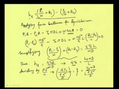
A Fanning friction factor is one quarter of the Darcy factor. Substituting a Fanning value into the Darcy equation without conversion understates straight-line loss by a factor of four. Label the convention beside every value imported from a chart, spreadsheet or calculator. NPTEL's fluid-mechanics recap distinguishes the two conventions and gives the underlying pipe-friction relationship.
This steady-flow model does not calculate hydraulic shock, transient pressure peaks, compressible aerated flow or a pump's internal efficiency. It is most useful for a defined, single-phase operating condition. Significant elevation or changing velocity between pressure-tapping locations also needs the corresponding energy-equation terms before a gauge difference can be called friction loss.
Add fittings and components without double counting
A documented local-loss coefficient can be used as delta p = K rho v squared / 2, provided the reference velocity and the conditions for that coefficient are known. Do not assume that a coefficient quoted for one fitting geometry, fluid regime or connection applies to every visually similar part. Low-Reynolds-number behavior can require additional correction.
An equivalent-length method is another representation of a fitting loss. Use either its equivalent length or its local-loss contribution in a given sum. Adding both counts the same resistance twice. Also check whether an assembly curve already includes its adapters, subplate or internal passages.
For valves, filters, coolers and quick couplings, prefer the selected component's pressure-flow curve at the relevant fluid conditions. A valve's nominal flow designation does not establish its actual differential pressure. Check the energized flow path and include both inlet and outlet paths when the actuator circuit requires them. Filters need consideration of clean-element loss, loading, bypass behavior and permissible differential pressure; the bypass setting is not an acceptable normal operating target.
Build a traceable pressure-loss worksheet
| Worksheet section | Required evidence | Calculation or review | Frequent error to avoid |
|---|---|---|---|
| Straight pressure line | Length, true bore, flow and warm/cold viscosity | Calculate velocity, Reynolds number and Darcy loss | Using outside diameter or reference-temperature viscosity |
| Straight return line | Actual actuator return flow and restrictions | Calculate independently from pressure line | Assuming return flow always equals pump flow |
| Fittings and adapters | Exact geometry and applicable coefficient or curve | Add one representation of each local loss | Adding both K and equivalent length |
| Directional or proportional valve | Selected path, command and pressure-flow data | Include all active paths under the same duty | Using a nominal flow label as a loss value |
| Filter and cooler | Fluid condition, loading state and component curve | Include justified operating differential pressure | Treating bypass activation as normal performance |
| Complete circuit | Defined operating state and measurement locations | Compare budget with useful load pressure | Adding parallel branches in series |
Supporting technical context: NPTEL: Darcy and Fanning friction factors and pipe loss, NPTEL: Fundamentals of Industrial Oil Hydraulics and Pneumatics. This evidence checklist does not establish a product rating or universal acceptance limit.
The table is an original evidence checklist, not a catalog of component ratings. The pipe-friction relationships are supported by the NPTEL fluid-mechanics reference. Component-specific entries require the actual selected drawings and curves.
Work through an illustrative laminar-flow example
Assume a horizontal straight line carrying 60 litres per minute, with a 20 millimetre internal diameter and a 10 metre length. For this example only, assume density of 850 kilograms per cubic metre and kinematic viscosity of 46 centistokes at the evaluated temperature. These are worksheet inputs, not Prance product specifications or a recommended operating condition.
Converting the flow gives 0.001 cubic metres per second. The mean velocity is approximately 3.18 metres per second. Reynolds number is approximately 1,384, so the fully developed laminar model is consistent for the straight-pipe calculation. The Darcy factor is approximately 0.0463. Substitution into the equation gives about 99,600 pascals, or 1.00 bar, of straight-line friction.
Now assume that separate, condition-matched evidence provides 2.0 bar through the active valve paths, 0.5 bar through the filter, 0.4 bar through the cooler, and 0.2 bar through fittings. The illustrative total is approximately 4.10 bar. Those additional values are assumed inputs to demonstrate summation; they are not measured results, acceptance limits or reusable estimates for an unidentified component.
At 60 litres per minute, 4.10 bar dissipates approximately 0.410 kilowatts, using loss power in kilowatts = Q in litres per minute multiplied by delta p in bar, divided by 600. This estimates hydraulic energy dissipation under the stated steady condition. It does not establish the final oil temperature, cooler capacity or electrical input; those require duty duration, heat balance and overall efficiency information.
Compare operating cases and preserve uncertainty
Repeat the worksheet for the governing flow directions, oil temperatures and machine functions. A warm calculation can look satisfactory while a cold start produces excessive filter differential pressure or inlet restriction. Conversely, a loss model using cold viscosity throughout a fully warmed shift may exaggerate continuous heat generation.
Change one input at a time when exploring improvements. Increasing bore changes velocity, Reynolds number and the friction factor, so simply scaling the previous pressure value by velocity alone can be misleading. Recalculate the complete section. Record the actual routing and minimum bend requirements before proposing a physically impractical replacement hose.
Keep an uncertainty column for missing bore dimensions, viscosity estimates and component curves. A total made from three reliable measurements and several guesses should not be presented to purchasing as a verified system requirement. Rank the unknowns by their likely effect and obtain the most consequential evidence first.
Verify measurements and prepare a component enquiry
Install and use pressure instrumentation only under the machine's approved service procedure. Isolate hazardous energy, use appropriate rated test equipment and account for stored pressure and suspended loads. Do not loosen a live connection to inspect flow or search for leaks with a hand. NIOSH's hazardous-energy guidance supports the need for planned isolation during maintenance.
Measure differential pressure across clearly identified boundaries with instruments suitable for the expected conditions. Record flow, fluid temperature, valve state, actuator motion and instrument identification alongside each result. Compare predictions and measurements at the same duty. A changing load between two readings can invalidate a subtraction even when both gauges are accurate.
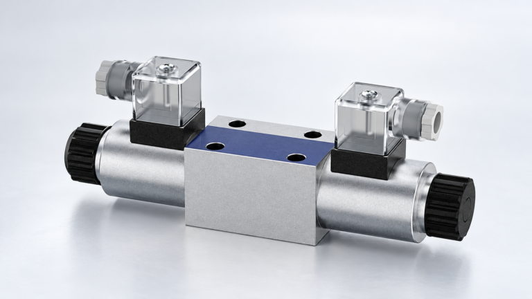
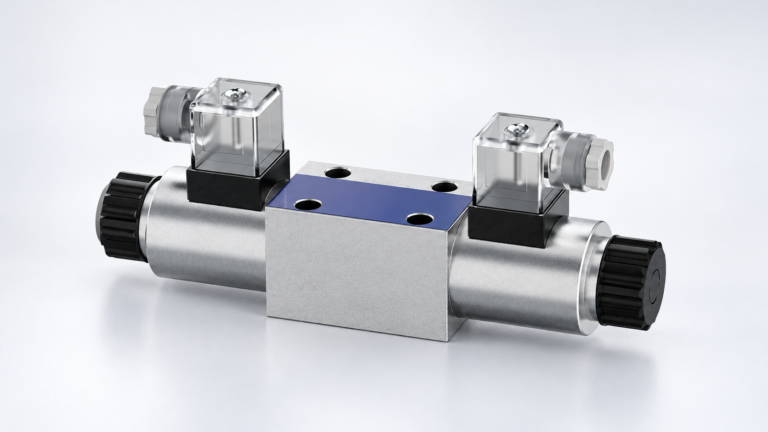
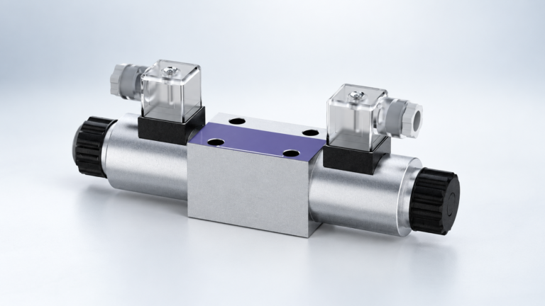
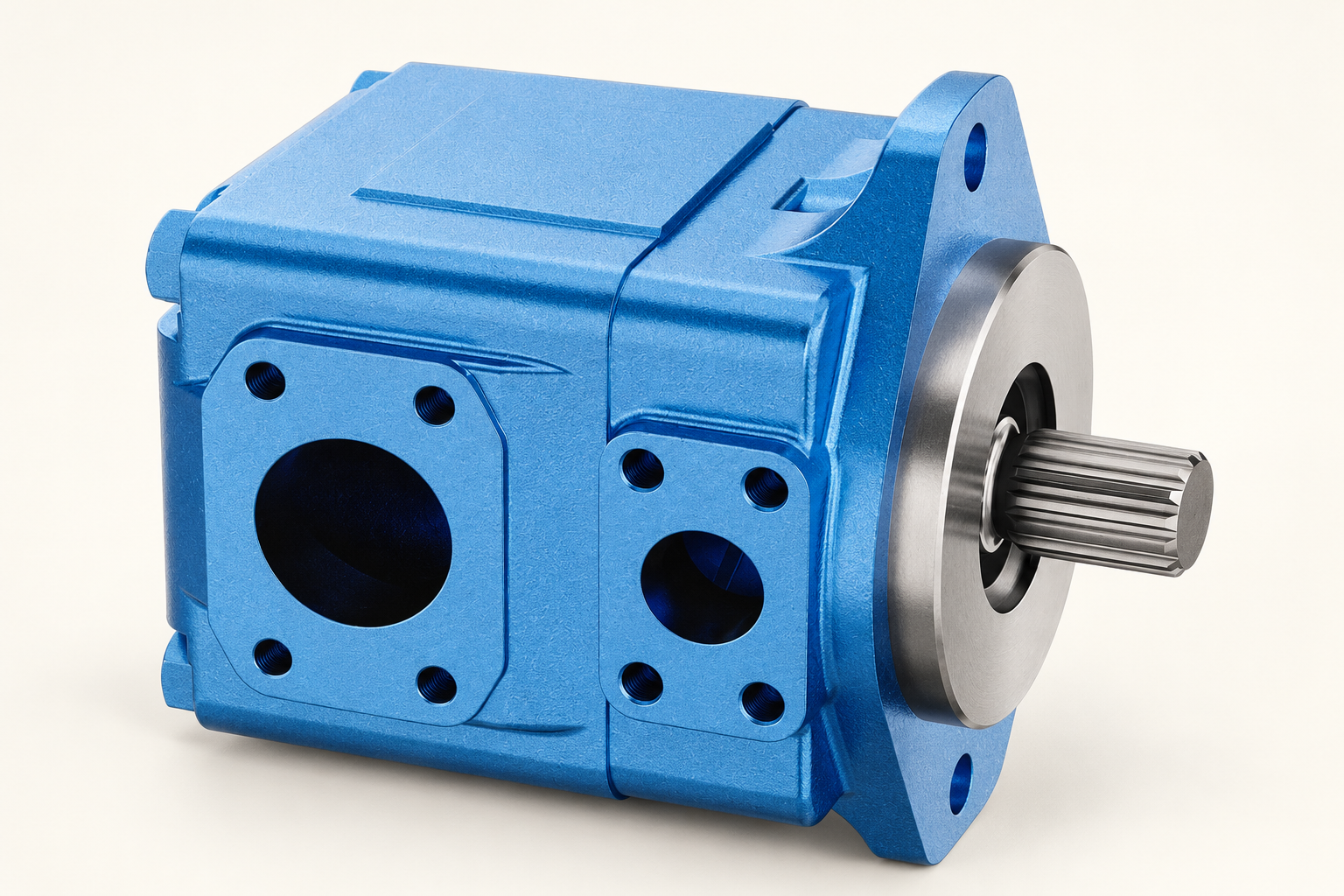
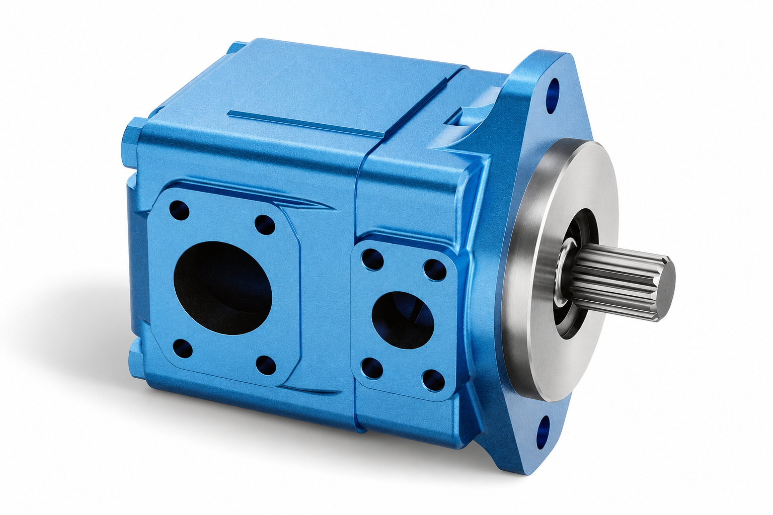
For a Prance pump or valve enquiry, provide the circuit, required useful load pressure, predicted loss budget, flow range, fluid, startup and operating temperatures, duty cycle and component interfaces. Ask for the selected configuration's relevant pressure-flow and fluid-condition data. An exterior product illustration can help identify the family and connections, but it cannot supply an internal-loss curve or authorize a universal operating limit.
Frequently asked questions
Can I calculate system pressure drop from pump pressure alone?
No. Pump outlet pressure includes useful load demand and losses along the active path. Identify the circuit state, flow and pressure boundaries, then calculate or measure the individual contributions. A single outlet reading does not locate the restrictive component.
Should I add every branch's pressure drop together?
Add losses along the same series path. Parallel branches require a separate flow and pressure analysis. Do not sum two alternative routes as though the fluid passes through both consecutively.
Is the Darcy factor the same as the Fanning factor?
No. The Darcy factor is four times the Fanning factor. Confirm the convention used by a source before entering it into a calculation; otherwise the straight-line result can be wrong by a factor of four.
Can a water pressure-loss calculator be used for hydraulic oil?
Only if its model accepts the appropriate oil properties and operating regime. A calculator based on a water-specific empirical relationship or fixed viscosity can give misleading oil results. Check its assumptions and units rather than relying on the interface label.
Does lower circuit pressure drop guarantee a cooler system?
Lower loss can reduce dissipated hydraulic power at the same flow, but final temperature also depends on duty, useful work, other losses and heat rejection. Recheck the thermal balance and machine function before treating a routing change as a guaranteed temperature solution.
Related products and engineering guides
T6 vane pump, vane pump range, valve-specific pressure drop, hydraulic motor efficiency calculation. Provide the circuit, fluid, duty and exact ordered configuration when requesting component-specific data.
University lesson: Mod-8 Lec-2 Pipe Flow: Losses in Pipes
This NPTEL university lecture explains pipe friction and local losses underlying the circuit calculation. Its civil-hydraulics examples explain fluid-mechanics principles; use the actual oil properties for an industrial circuit.
Technical references
- NPTEL: Darcy and Fanning friction factors and pipe loss
- NPTEL: Fundamentals of Industrial Oil Hydraulics and Pneumatics
- NIOSH: hazardous-energy isolation
Sources support the stated principles and method scope. Illustrative inputs and another manufacturer’s documents do not establish Prance component ratings, warranties or brand affiliation.