Wenzhou Prance Hydraulic Equipment Co., Ltd

Pump Startup Pressure Spikes: Valve Position, Load, and Control Delay
A hydraulic pump pressure spike during startup usually means delivery reaches a restriction or loaded circuit before the intended unloading or displacement control has settled. The pressure may then fall to a normal running value, leaving an ordinary gauge with little evidence of the event. Diagnose the first seconds as a sequence: drive starts, pump produces flow, valves assume their positions, controls respond, and the load becomes connected. This article focuses on that startup sequence. It does not replace a general surge analysis or the pump manufacturer’s commissioning procedure.
Establish whether the event is really a pressure spike
A high reading is not automatically a transient overshoot. A circuit that remains at high pressure until an unloading command arrives has a sustained startup load. A brief peak above the later steady value is a different event. A slow gauge may show either as a twitch, while a controller may retain only the largest sample. Identify the instrument and what its displayed number represents before comparing readings.
Capture the start command and pressure on the same timeline. Where the approved test arrangement allows it, include shaft speed, unloading command, valve actuation, and pump-control signal. The goal is to determine which transition precedes the rise. Merely recording the highest pressure after several starts loses the causal order that distinguishes a late valve from a slow pump regulator.
Choose the measurement arrangement through a competent test engineer. Sensor range, response, connection geometry, filtering, and acquisition rate affect the result. There is no universal sampling rate appropriate to every startup event. A record with too few points across the rise cannot demonstrate that the true peak stayed below a component limit.
Trace the flow path before the drive turns
Read the schematic in its de-energized state. Trace pump delivery through each valve that must pass flow before an actuator is commanded. Do not assume the valve is in its running neutral position while power is first applied. Spring positions, retained detents, pilot availability, and electrical sequencing can produce different initial states.
For a fixed-displacement pump, determine where its delivery can go when work ports are blocked. A closed outlet without a suitable protective route is not an acceptable test condition. NPTEL’s hydraulic-system introduction explains why positive-displacement delivery against a dead end requires pressure protection. This principle is different from startup advice sometimes given for centrifugal water pumps.
For a variable pump, identify the control actually supplied. Pressure compensation, load sensing, and electrical displacement commands have different startup conditions. A product-family name alone does not establish the initial swashplate position, response time, or unloading logic. Obtain the complete code and control documentation rather than inferring behavior from the pump’s appearance.
Distinguish unloading from pressure relief
An unloading arrangement provides an intended low-load path when pump delivery is not needed by the work circuit. A pressure-relief arrangement limits pressure when the relevant setting is reached. They may share some physical principles, but their role and sensing connections differ. A circuit that starts by sending full pump flow across a high-pressure relief may impose a substantial startup load even when the relief operates correctly.
NPTEL’s unloading-valve lesson describes diversion of pump delivery to tank through pilot operation. Its worked double-pump material also shows that unloading one supply can change which flow reaches the main circuit. These are explanations of circuit functions, not instructions to modify a particular machine’s spring or pilot connections.
Confirm whether the installed machine requires an electrical command, pilot pressure, or a pressure-dependent transition to unload. Then verify that prerequisite at the instant the motor begins rotating. A correct command appearing after pressure rises does not prove the unloading sequence was correct during the event.
Use timing to separate likely mechanisms
The following author-proposed table organizes evidence for a startup investigation. It provides no universal pressure or delay limits. Compare each observation with the original machine sequence and the ratings of the exact installed components.
| Pressure-event pattern | Mechanism to investigate | Evidence that helps distinguish it |
|---|---|---|
| Rise begins before unloading command | Control sequence connects load too early | Start command and unloading output on one timeline |
| Command is present but low-load path opens later | Valve actuation or pilot availability | Coil signal, pilot pressure, and upstream/downstream pressure |
| Peak follows first work-valve movement | Load connection or spool transition | Valve command, actuator motion, and local pressure |
| Cold start differs sharply from warm restart | Viscosity, restriction, or control response | Fluid condition and matched starting procedure |
| Pump-outlet peak differs from remote peak | Location-dependent transient behavior | Synchronized sensors at approved test points |
| High pressure persists after acceleration | Sustained loading rather than only overshoot | Pressure trace after shaft speed stabilizes |
A sequence table should include expected states as well as observed states. For example, “unloader energized” is not enough if energizing that particular valve closes rather than opens its unloading route. Label the physical function, then record the electrical condition that produces it.
Check the drive and pump controls together
A motor starting method can change acceleration, but reduced electrical inrush does not automatically mean reduced hydraulic load. If pressure builds while the motor is still accelerating, the drive may experience the combination of acceleration demand and hydraulic torque. Review both with the drive and hydraulic specifications rather than treating an electrical starter adjustment as a hydraulic repair.
For screening, hydraulic output power in kW equals pressure difference in bar multiplied by flow in L/min and divided by 600. As a hypothetical example, 40 L/min at 150 bar is 10 kW of hydraulic power. The actual shaft input would be higher because of losses. This example illustrates why a high-pressure start matters; it is not a startup rating or an allowable peak for a Prance pump.
A pressure-compensated pump may reduce displacement after pressure rises, but its control does not eliminate the need to assess transient protection. Likewise, an electronic displacement limit must be checked for the actual initial command and fail state. Verify the installed logic against the approved design before changing pressure settings or ramp parameters.
Compare cold starts and restarts fairly
Cold oil can change inlet losses, valve movement, and control response. A machine that starts quietly when warm may still have an unresolved cold-start problem. Record fluid temperature and grade, reservoir condition, and shaft speed. Use the approved cold operating limits; do not repeatedly start outside them in an attempt to obtain a clearer trace.
A restart after a brief stop can present a different hydraulic state from the first start of the day. Accumulators, trapped branches, and pilot lines may retain pressure or discharge on different timescales. Confirm their actual condition through approved measurement and isolation procedures. Never assume a stopped pump means the entire circuit is depressurized.
If the symptom appeared after maintenance, compare the replaced components and settings with the previous documented configuration. A changed spool function, incorrect check-valve orientation, or different control code can alter the initial flow path even when the new parts fit mechanically. Investigate those differences before concluding the pump has an internal defect.
Match the product to the control requirement
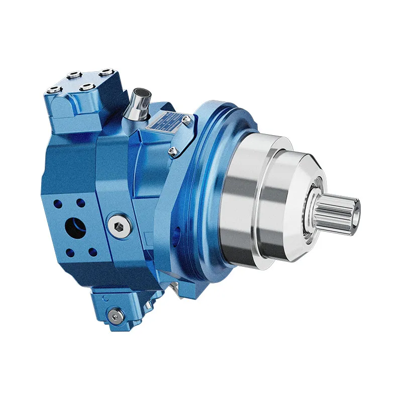
Prance’s Variable Displacement Pump OEM A10VO 31 Series page is a relevant product entry for a variable-pump inquiry. The original photographs show the offered external configuration. They do not verify startup displacement, compensation settings, response time, or compatibility with an existing machine controller. Obtain confirmation for the full ordered code and actual circuit.
A useful request includes the existing pump identification, schematic, start sequence, drive speed, fluid condition, and a time trace of the event. State the measurement location and whether the result is a peak, filtered reading, or steady value. Ask the supplier to assess the specific operating condition rather than simply quoting a higher nominal pressure version.
Before installing a replacement, agree which features must remain equivalent and which may change. Any revised control arrangement needs a defined acceptance test. A pump that reaches normal running pressure after startup has not necessarily passed a transient test, and a quieter start alone does not establish acceptable peak pressure.

Validate a correction against the complete sequence
Secure loads, isolate stored energy, and follow the machine’s safe test procedure before installing instruments or changing components. Keep pressure protection effective. Do not block returns, defeat an interlock, or bypass a relief valve to make a suspected cause easier to observe. Stop if the machine moves unexpectedly or measured conditions exceed approved limits.
After a correction, repeat the same permitted starting condition using the same measurement setup. Compare pressure peak, duration, drive acceleration, and valve timing. Also check the next commanded work movement: a delay added to reduce startup pressure must not create an unsafe lack of supply or an unexpected actuator response later in the cycle.
Document the final configuration and acceptance limits with the evidence. Include cold and warm conditions when both are part of the approved operating envelope. The useful outcome is a verified sequence that keeps the circuit within its requirements, not simply a lower number obtained under a different test condition.

Frequently asked questions
Why does the running gauge look normal after a hard start?
A short event can end before the gauge or display settles. Normal steady pressure therefore does not rule out startup overshoot. Use an approved measurement arrangement capable of resolving the event and identify what the displayed peak function actually captures.
Will a soft starter always remove the pressure spike?
No. It changes the drive’s electrical and acceleration behavior, but the hydraulic circuit still needs a suitable initial flow path and control sequence. Review the combined drive and hydraulic response rather than assuming a starter setting solves both.
Should the relief pressure be increased to stop startup chatter?
Not without an approved diagnosis. Increasing a setting can increase component loading and conceal the original cause. Identify the valve function, flow path, actual pressure trace, and permitted settings before proposing an adjustment.
Can an accumulator be added as a universal solution?
No. Accumulator sizing, placement, charging, protection, and stored-energy safety require a circuit-specific design. It may change the transient, but it can also alter later machine behavior and maintenance hazards. Do not use one as a substitute for understanding startup logic.
What evidence is most useful for a supplier review?
Send the complete pump and valve codes, circuit drawing, start-command sequence, fluid temperature, shaft-speed record, and pressure trace with measurement details. Explain whether the symptom occurs on the first cold start, every restart, or only after a particular machine condition.
Related product and engineering resources
Variable Displacement Pump OEM A10VO 31 Series, hydraulic pump product range, Hydraulic Shock Pressure: Causes, Calculation, and Protection, Hydraulic Pump Outlet Check Valves: Reverse Flow and Shutdown Isolation. Confirm the complete product code and application requirements when requesting a configuration review.
Technical references
- NPTEL: positive-displacement supply and pressure protection
- NPTEL: unloading valve
- NPTEL: unloading and double-pump circuits
Further learning: hydraulic pumps
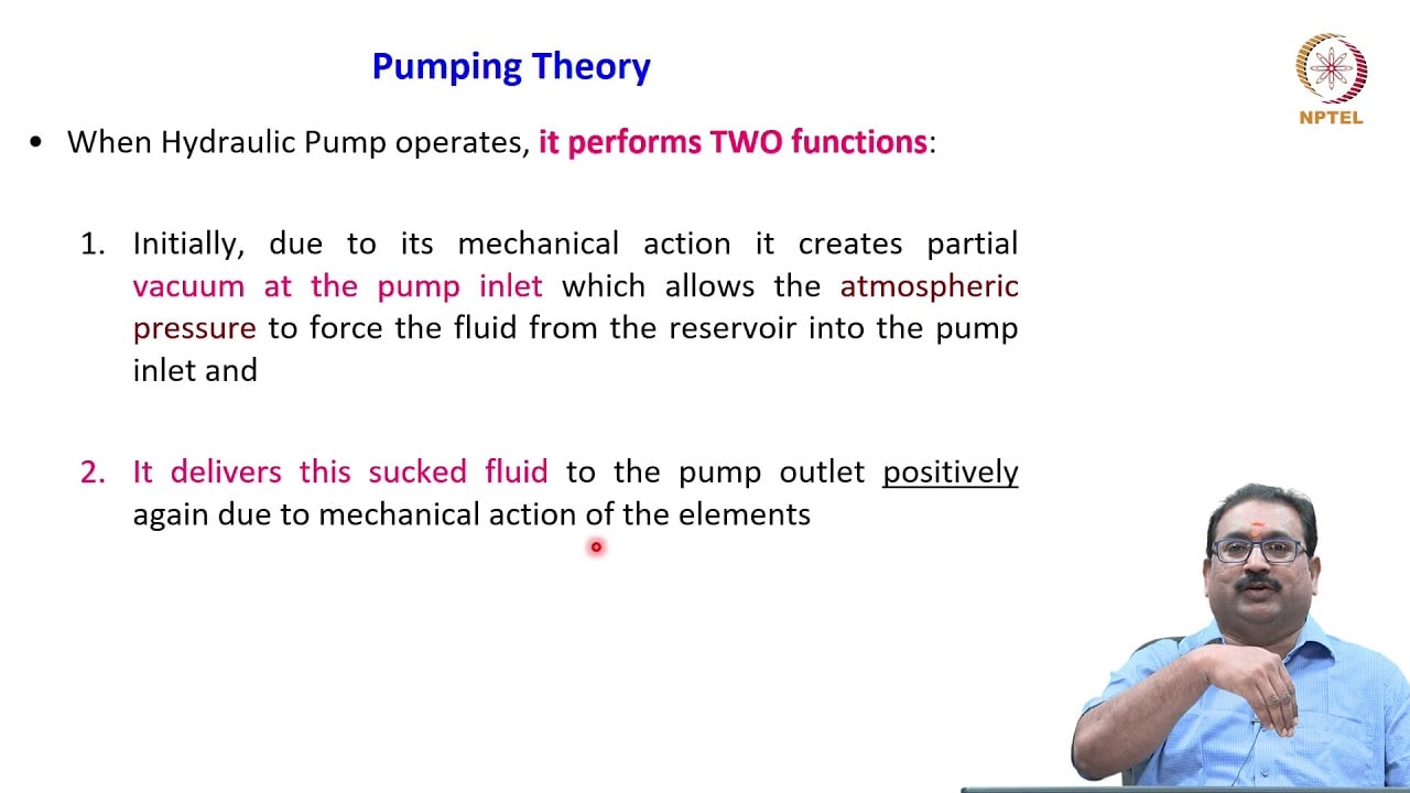
3.2 – Hydraulic Pumps by NPTEL-NOC IITM provides background on pump operating principles. This NPTEL lesson explains the pump or valve fundamentals used here. It does not demonstrate the exact startup, steering, or cavitation test described in this article. It supplements the component fundamentals; it is not a test procedure for the complete circuit discussed above.