Wenzhou Prance Hydraulic Equipment Co., Ltd

Pump Shaft-Seal Air Ingress: Why a Dry Seal Can Still Admit Air
A hydraulic pump shaft seal vacuum leak can admit air while leaving the outside of the pump apparently dry. This is possible when the fluid space behind that seal operates below atmospheric pressure and a leakage path exists across the seal or its installation. The pressure difference drives air inward instead of oil outward. However, not every pump connects its shaft-seal chamber to the inlet. Confirm the actual internal routing before blaming the seal. A reliable diagnosis combines the correct component drawing, inlet-pressure measurements, operating conditions, and controlled checks of other air-entry paths.
Why no visible oil does not prove a tight seal
An inspection for oil drips answers a limited question: is liquid escaping under the conditions being observed? It does not establish gas tightness under a different pressure direction. A stopped pump can look clean because its seal chamber has little positive head. During operation, the same chamber may experience a pressure deficit that encourages inward leakage.
The relevant pressure is the pressure immediately behind the seal, not the outlet gauge reading. A high discharge pressure can coexist with a low inlet pressure. Conversely, some piston pumps have a separately drained housing whose pressure must be assessed independently. Treating every drive-shaft seal as part of the suction passage can therefore produce the wrong diagnosis and an unsuitable repair.
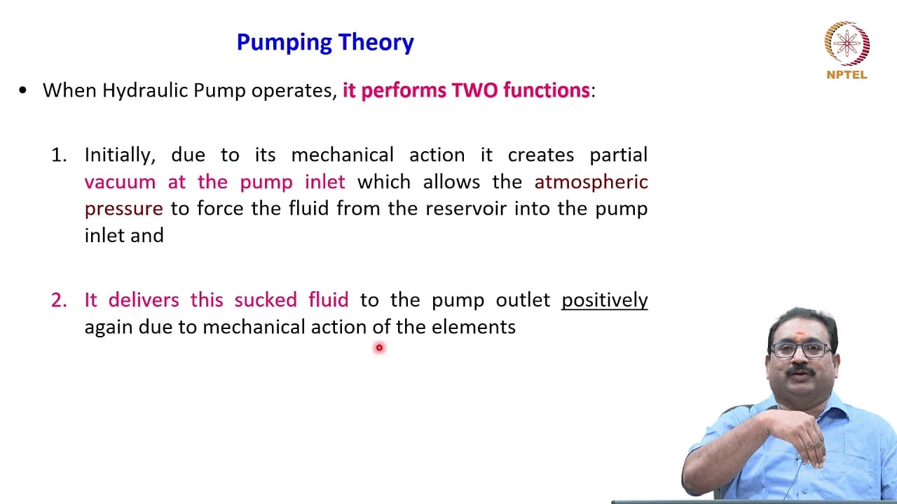
NPTEL’s external gear-pump explanation describes expanding inlet chambers and the resulting pressure reduction. That establishes the suction mechanism. It does not establish the seal-chamber arrangement of every pump sold under a general family name.
Establish which fluid space the seal actually sees
Start with the complete pump code, section drawing, and installation instructions. Identify whether the shaft-end space communicates with the inlet, an internal return passage, or a separately drained housing. Note any intermediate seals, bearing cavities, and drain connections. If the drawing is unavailable, request confirmation from the supplier rather than interpreting the photograph as an internal diagram.
Next, identify the seal construction and intended pressure direction. A radial lip seal, a mechanical face seal, and a packing arrangement cannot share one generic acceptance limit. SKF’s seal-analysis guidance treats pressure differential, counterface condition, lubrication, and installation as interacting selection factors. Its limits must be applied to the documented seal design, not transferred to an unidentified pump assembly.
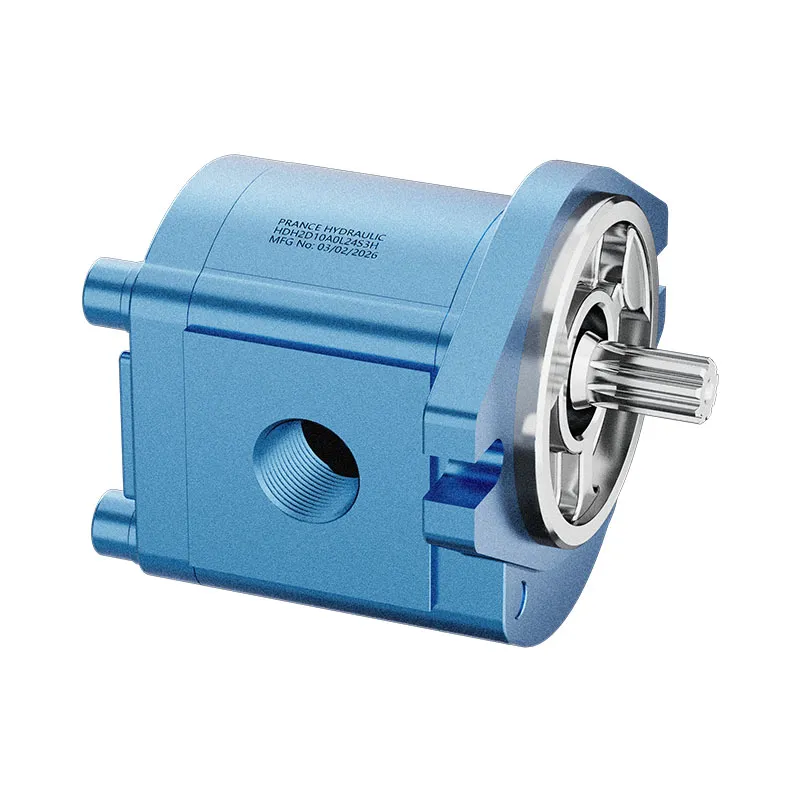
For an HG internal gear pump under review, the purchasing question is consequently specific: what is the pressure range at this ordered build’s shaft-seal chamber, and what installation arrangement is approved? The product name alone is insufficient to answer either question.
Separate air ingress from vapor cavitation
Air ingress means external gas crosses a leakage path into the hydraulic fluid. Vapor cavitation means local pressure becomes low enough for the liquid to form vapor cavities. Dissolved gas can also emerge as pressure falls. These mechanisms can occur together, and all can produce noise or unstable delivery.
Foam at the reservoir and irregular actuator motion are useful clues but do not locate the source. A return line discharging above the oil surface, a suction vortex, a loose inlet connection, or an unsuitable reservoir arrangement can introduce air without a defective shaft seal. Pump wear can coexist with any of them.
Record what changes with speed, temperature, fluid level, and load. A cold-start symptom that improves as viscosity falls suggests investigating inlet restriction. A symptom appearing after a coupling change gives mounting and shaft motion more relevance. Neither pattern proves the cause on its own.
Build a measurement plan before replacing parts
Use approved test points and instruments suitable for the pressure range. The inlet measurement should capture the conditions at the pump connection as closely as the installation permits. State whether the reading is absolute pressure or gauge pressure; a vacuum gauge reading cannot be compared directly with an absolute-pressure specification.
Record fluid temperature and pump speed alongside pressure. A value recorded at warm idle may miss the cold, high-speed condition that produces the complaint. Where transients matter, a slow dial gauge may conceal the minimum pressure. Choose the recording method with the equipment engineer and preserve the time relationship between signals.
| Observation | What it supports | What it does not establish | Next check |
|---|---|---|---|
| Dry seal exterior while running | No obvious outward oil escape at that moment | Gas tightness under inward differential | Confirm chamber routing and pressure |
| Inlet pressure falls as speed increases | Rising inlet demand or restriction | A shaft-seal defect by itself | Check hose condition, valves, fluid viscosity and inlet limits |
| Foam appears after maintenance | A changed air-entry or return condition | Which connection admits air | Review disturbed joints and reservoir return arrangement |
| Housing pressure exceeds the build limit | A drain or operating-condition concern | That a stronger seal solves the system fault | Verify drain routing and permitted back pressure |
| Noise remains after seal replacement | Original diagnosis may be incomplete | That the replacement seal is necessarily defective | Repeat the same controlled measurements |
These are diagnostic distinctions, not universal pass/fail thresholds. Use the pump and seal documentation for numerical limits.
Inspect the complete inlet path
With the machine isolated and stored energy controlled, inspect the inlet connection, hose, clamps where applicable, O-rings, and sealing faces. A joint can admit air without dripping because the pressure direction differs from a pressure-line leak. Look for hose deterioration, unsupported weight, loose adapters, or an inlet valve that is not fully open.
Check reservoir level using the approved operating condition. Fluid displaced into cylinders or accumulators may change the level substantially. A satisfactory level with the machine parked does not guarantee adequate submergence during the worst operating state. Examine the return location and whether turbulence can reach the suction region.
Do not insert an unapproved transparent hose to make bubbles visible. It may lack vacuum resistance, temperature capability, or fluid compatibility. An approved observation point or properly specified instrument is preferable to a temporary modification that changes the fault being investigated.
Keep seal testing away from rotating hazards
Do not reach around a running coupling, remove a guard for an improvised leak test, or place loose material near the shaft. NIOSH’s hazardous-energy guidance applies to servicing activities that expose workers to unexpected startup or stored energy. Isolate the machine before physical inspection, disassembly, or adjustment according to its approved procedure.
If a specialist proposes a dynamic leak-location method, obtain a written method that addresses guarding, fluid compatibility, contamination, fire risk, and instrument arrangement. Avoid using volatile spray or applying grease as an informal cure. A temporary change in sound can be misleading and may introduce contaminants.
A stopped static test may also be inconclusive. Shaft rotation, temperature, runout, and differential direction can alter sealing behavior. State explicitly what a test reproduces and what it leaves untested so that an inconclusive result is not reported as proof of a sound seal.
Examine shaft and installation conditions
If evidence supports opening the assembly, preserve the removed seal and photograph its orientation before cleaning. Examine the lip or sealing face, spring where present, installation damage, housing bore, and shaft counterface. Distinguish an installation cut from wear developed during service. Compare the findings with the seal manufacturer’s failure-analysis guidance.
A replacement seal can fail again if the shaft has a wear track, excessive movement, or an unsuitable surface finish. Coupling misalignment and unsupported mechanical loads deserve review when the seal damage pattern or maintenance history suggests shaft motion. Use the pump’s mounting and shaft-load limits; do not assume the seal itself carries alignment errors.
Confirm material compatibility with the actual fluid and temperature range. Matching external dimensions is only one part of replacement selection. The complete seal specification, pressure direction, installation tooling, and counterface acceptance matter equally.

Verify the repair under repeatable conditions
Repeat the original operating sequence after repair using the same measurement points. Compare inlet pressure, temperature, speed, delivery stability, and visible reservoir behavior. A quieter warm machine is an incomplete comparison if the original fault occurred during a cold start.
Define acceptance before testing. It should include compliance with documented inlet and housing limits, no abnormal air-related symptoms, stable required machine performance, and no new leakage. If symptoms persist, return to the diagnostic tree instead of fitting progressively stronger seals without a verified cause.
Retain the baseline and post-repair traces with the work order. They provide evidence for the next failure review and help distinguish a recurring inlet problem from a new component defect. Avoid claiming a guaranteed lifetime extension from a single successful test.

What to send with a technical inquiry
For a Prance configuration review, provide the complete pump code, installation orientation, circuit drawing, fluid grade, temperature range, speed range, inlet geometry, and any housing-drain details. Add synchronized pressure observations and the conditions that reproduce the noise or foaming. State whether the complaint began after changing the hose, coupling, seal, or reservoir arrangement.
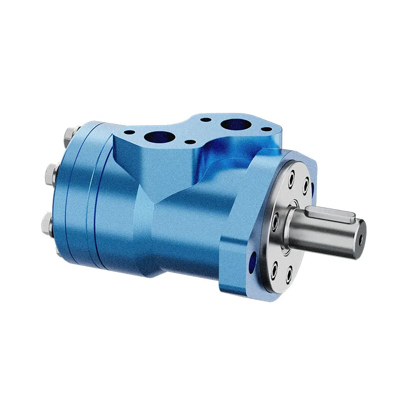
Ask the supplier to identify the correct seal-chamber pressure range and approved replacement procedure for that build. For an internal gear pump, do not borrow external gear-pump routing assumptions. Exterior product photographs help identify the component family and connection locations, while the verified drawing controls the internal interpretation.
Frequently asked questions
Can a pump shaft seal leak air without leaking oil?
Yes, where its fluid-side pressure is below atmospheric pressure and a leakage path exists. Whether this applies to a specific pump depends on the shaft-seal chamber’s routing and operating pressure. A dry exterior alone cannot confirm or exclude it.
Does foam prove that the shaft seal is faulty?
No. Foam can result from other inlet leaks, reservoir turbulence, return-line aeration, or gas released from the fluid. Check the complete path and operating conditions before assigning the fault to one seal.
Should the discharge gauge be used to assess seal pressure?
Not unless the verified design connects that pressure to the seal chamber. Inlet, outlet, and separately drained housing pressures can differ substantially. Use the pressure relevant to the actual seal location.
Can a higher-pressure seal fix repeated failures?
Only if an approved engineering review establishes that it is the correct design. It does not correct excessive drain pressure, inlet restriction, shaft movement, installation damage, or fluid incompatibility. Address the cause before choosing a replacement.
Is a successful stopped leak test enough?
It may not reproduce the running condition. Rotation, temperature, shaft movement, and pressure direction can affect leakage. Document those limitations and use the machine manufacturer’s approved acceptance procedure for the actual duty.
Related product and engineering resources
Internal Gear Pump HG for Plastic Injection Molding Machine, hydraulic pump product range, What evidence should guide a hydraulic pump shaft-seal review?, Hydraulic Pump Outlet Check Valves: Reverse Flow and Shutdown Isolation. Confirm the complete product code and application requirements when requesting a configuration review.
Technical references
- NPTEL: external gear-pump suction and displacement
- NIOSH: preventing uncontrolled release of hazardous energy
- SKF: seal analysis, shaft condition and operating environment
Further learning: hydraulic pumps
3.2 – Hydraulic Pumps by NPTEL-NOC IITM provides background on pump operating principles. Use this lesson for the energy-conversion fundamentals. Seal leakage, relief-groove timing and spline lubrication require the specific component documentation, not inference from a general lesson. It supplements the component fundamentals; it is not a test procedure for the complete circuit discussed above.