Wenzhou Prance Hydraulic Equipment Co., Ltd

Sequence Valve vs Relief Valve: Sequencing Is Not Pressure Protection
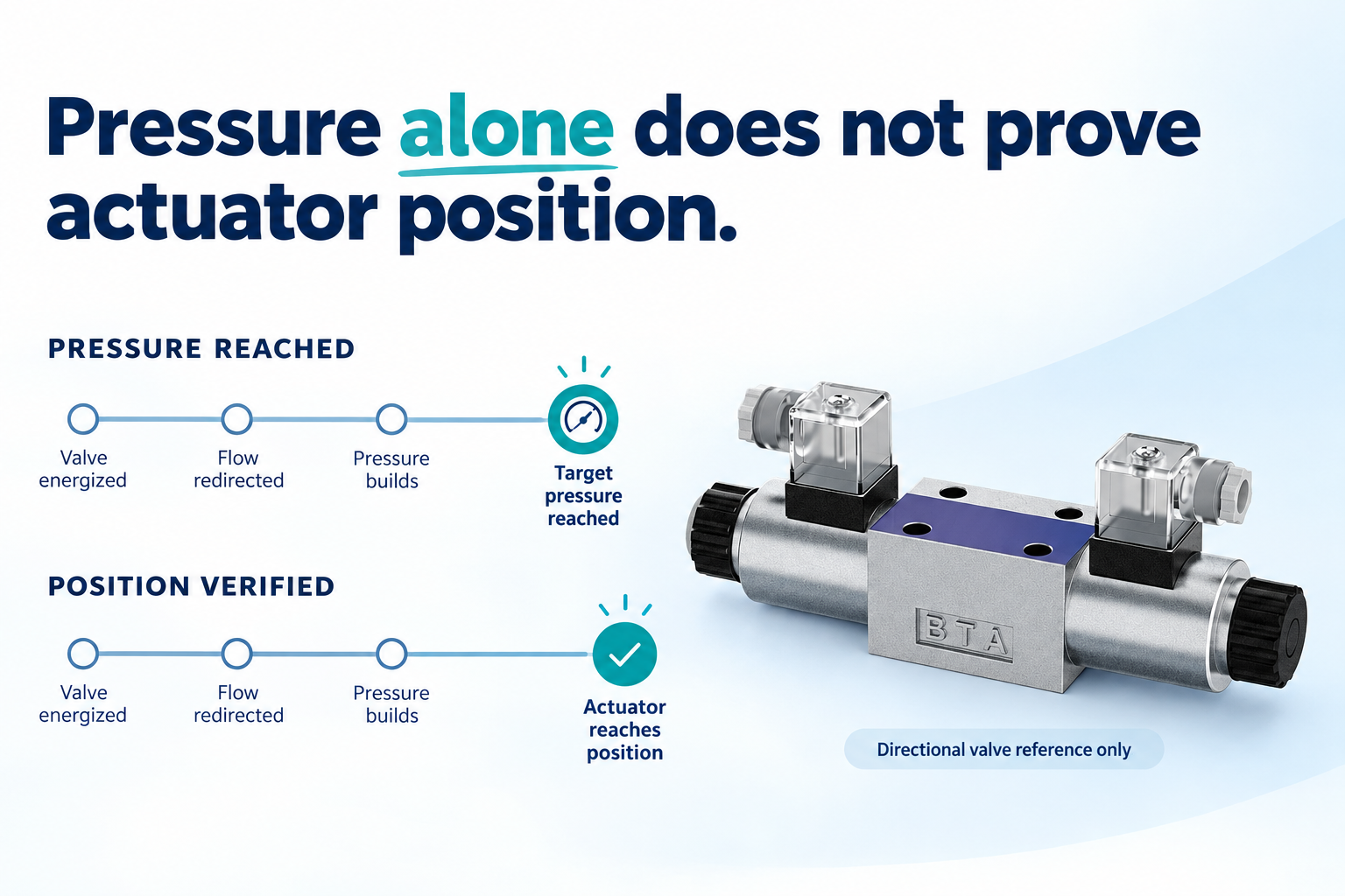
A hydraulic sequence valve vs relief valve comparison is about the flow’s destination and the valve’s job, not simply the fact that both respond to pressure. A relief valve normally diverts flow toward a low-pressure return to limit upstream pressure. A sequence valve normally opens a route to another working circuit when its pilot condition is satisfied. A conventional sequence function therefore cannot automatically replace the system’s pressure protection. Its downstream pressure, pilot source and drain arrangement must all match the circuit. Reaching a pressure threshold also does not prove that an actuator has reached a safe position.
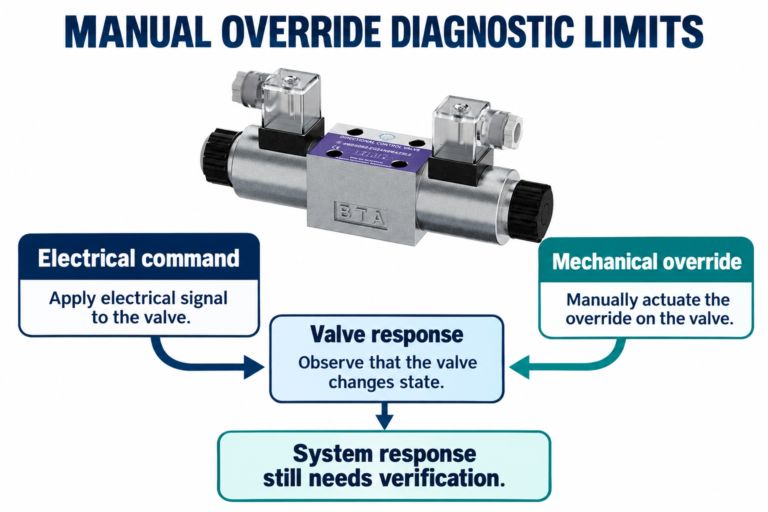
This guide explains ordinary pressure-sequencing principles and their limits. Special multifunction cartridges can combine functions, but their exact symbols and documentation govern. The pictured 4WE directional valve is included only as real catalog context for a wider hydraulic circuit; it is not presented as a sequence valve or relief valve.
Follow the flow after the valve opens
Consider a pump supplying a clamp and a second actuator. A sequence function can delay supply to the second branch while the first branch builds pressure. When the monitored pressure reaches the opening condition, flow becomes available to the next function. The outlet is therefore a working passage, and its pressure can change as the second actuator meets its load.
Contrast that with a conventional relief valve connected from the pressure supply to a return destination. Opening creates a route for flow that prevents the upstream pressure from rising without the intended limit. The return route, capacity and pressure setting must be suitable for that protective job. A valve that merely supplies another loaded branch does not necessarily provide an equivalent escape path.
The distinction is functional rather than cosmetic. Two housings may look similar while their internal pilot and drain passages differ. A matching thread, cavity or pressure-adjustment screw is not sufficient evidence of interchangeability. Read the full hydraulic symbol and the manufacturer’s description for the complete ordering code.
Compare sequence, relief and reducing functions
The following qualitative comparison is consistent with the university hydraulics material linked below. It distinguishes general functions rather than rating a specific component. ISO 4413 provides general hydraulic-system safety context; machine-specific protective design still requires the applicable documents and risk assessment.
| Function | Main pressure reference | What opening or regulation accomplishes | What it does not automatically prove |
|---|---|---|---|
| Sequence valve | Specified pilot pressure, often upstream | Makes flow available to a subsequent working branch | First actuator position or independent supply-pressure protection |
| Relief valve | Pressure at its specified sensing point | Diverts sufficient flow through its designated relief path | Correct machine sequence or safe load holding |
| Pressure-reducing valve | Usually the controlled downstream pressure | Maintains a lower branch pressure through its regulating action | Full-system relief capacity or confirmation of actuator position |
| Directional valve | External command, depending on actuation | Selects connected flow paths | Pressure limitation unless a separate documented function provides it |
Use this table to ask better circuit questions. Do not select a valve solely from a function name when a combined cartridge, remotely piloted stage or integrated manifold changes the actual connections.
Pressure is an imperfect signal of completed motion
In a simple clamp circuit, pressure may rise when the clamp contacts the workpiece. That is useful information, but pressure can also rise when a hose is obstructed, an actuator jams or the wrong part prevents travel. The sequence valve sees the pilot condition, not the reason that condition exists.
This matters when the next operation would be dangerous without completed clamping. An opening sequence valve cannot by itself establish correct contact, adequate holding force or verified position. Where the risk assessment requires position or force confirmation, use the appropriate validated sensing and control arrangement. Do not treat a pressure-only sequence as a substitute for required safeguarding.
A pressure rise can also occur dynamically. Starting transients and changing loads may briefly satisfy the pilot condition. Whether that causes premature movement depends on the valve’s response and the rest of the circuit. Analyze the real duty cycle rather than assuming the pressure signal is a slow, clean ramp.
Understand the drain before discussing the setting
Many conventional sequence valves use an external drain so the pilot or spring chamber has a defined pressure reference separate from the working outlet. This can make the sequence condition less dependent on outlet pressure than an arrangement that references the same loaded outlet. Exact behavior depends on the valve design and effective areas.
External drain does not mean “connect anywhere that eventually reaches the tank.” A shared return can develop backpressure from other functions or from a restricted filter. If that pressure acts on the control chamber, the opening condition may shift. Follow the documented drain-pressure limit and routing instructions instead of assuming the line always has zero pressure.
Confirm whether the drain must remain separate, whether the pilot is internal or external, and what pressure is permissible at each control port. A blocked drain can alter behavior dramatically. Never loosen a drain connection on an energized circuit to see whether operation improves; trapped fluid and unexpected motion remain hazards.
Keep downstream load pressure in the analysis
The sequence outlet supplies a working circuit, so the second actuator’s load matters. Once the sequence valve opens, the pump must provide the pressure needed for that branch together with the losses across the active flow path. If downstream demand approaches the available supply pressure, behavior may differ from the assumed sequence.
Opening pressure, reseat behavior and the pressure needed to pass the required flow are not necessarily identical. A catalog setting taken at one test flow may not predict the pressure drop at another. Review the valve’s pressure-flow curves, pilot arrangement and expected flow rather than assigning every stage one nominal pressure number.
For an illustrative energy check, hydraulic power lost through a restriction can be estimated from pressure drop multiplied by flow. In common engineering units, loss in kilowatts is approximately pressure drop in bar times flow in litres per minute divided by 600. A hypothetical 10 bar drop at 30 litres per minute represents about 0.5 kW of hydraulic power converted largely to heat. These are example inputs, not recommended settings or ratings.
This calculation helps explain why a continuously throttling sequence stage can increase the cooling burden. It does not establish temperature rise by itself: reservoir volume, ambient conditions, cooler performance and duty cycle also matter. Evaluate loss over the actual cycle rather than only at the instant the valve opens.
Check reset and reverse flow
The machine must return to its initial state as well as execute the forward sequence. Some sequence-valve arrangements include a reverse-flow check; others require a separate route. Confirm the symbol and ordering code. Do not infer a check valve from the product family’s general description.
Trace the return path for both actuators during reset. Identify trapped volumes, pressure retained behind checks and any pilot pressure that must decay before the next cycle. A sequence that works once but fails on restart may involve retained pressure or an incomplete reset, rather than an incorrect nominal spring setting.
Reverse flow also affects the return filter and connected equipment. A return route that is acceptable at one flow can develop excessive backpressure during simultaneous motion. Include those conditions when reviewing external drains, seals and the relief destination. A sequence valve should be evaluated within the entire circuit, not as an isolated adjustable part.
Diagnose the symptom before touching an adjustment
For early second-stage motion, compare the pilot pressure record with the commanded motion and, where available, position feedback. Check for load changes and transients. For a second stage that never starts, verify supply availability, pilot routing, downstream demand and drain conditions. An adjustment alone cannot resolve every cause.
Use designated pressure test points and instruments rated for the application. State where each reading was taken, whether it is steady or transient, and the operating condition. A reading upstream of a long line cannot automatically be substituted for the pressure at the valve’s actual sensing port.
Before opening or servicing equipment, follow the machine’s hazardous-energy procedure. Isolate electrical and hydraulic sources, secure gravity loads and address stored energy. NIOSH guidance explains why a stopped machine can still contain dangerous energy. This article supplies no authorization to defeat interlocks or adjust an operating machine.
Build a useful specification or replacement inquiry
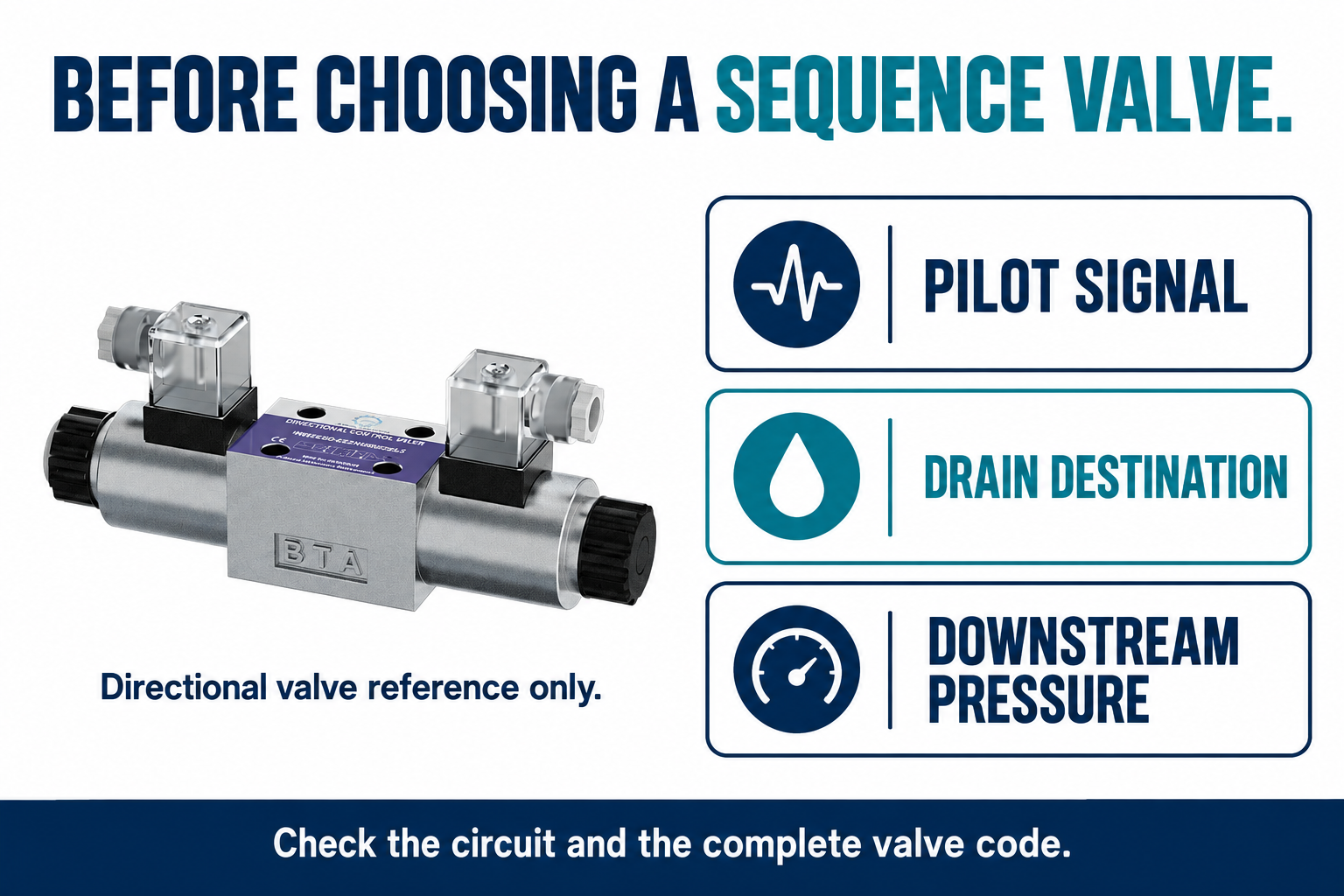
Provide the complete circuit symbol, valve code, pilot source, drain destination and flow in both directions. Include the first and second actuator loads, required sequence behavior, cycle timing and the existing system pressure protection. Describe whether confirmation is based on pressure alone or additional sensors.
Ask the supplier to distinguish opening, full-flow and reset conditions. Request applicable drain and outlet-pressure limits, the reverse-flow arrangement and the relevant pressure-flow curves. If replacing a valve, confirm the cavity, mounting, seals and fluid compatibility in addition to its pressure range.
The final review should state what proves that the next movement is permitted and what independently protects the supply against excessive pressure. When those two responsibilities remain clear, a sequence valve can support reliable motion without being mistaken for a universal safety or relief device.
Frequently asked questions
Can a relief valve be used as a sequence valve?
Some valves can be configured for more than one pressure-control function, but only when their pilot, outlet and drain arrangements support the intended circuit. A conventional relief valve should not be substituted by appearance or nominal setting. Obtain documentation for the exact configuration.
Does a sequence valve protect the pump from overpressure?
Not automatically. Its ordinary job is to supply another working branch after a pilot condition is reached. Provide the pressure protection required by the complete hydraulic system. A multifunction component counts only when its documented configuration supplies that protective function.
Why does a sequence valve need an external drain?
In many designs it gives the control chamber a pressure reference separate from the working outlet. Backpressure in that drain can still affect operation. Use the manufacturer’s port description and limits; not every sequence-valve architecture uses the same arrangement.
Does reaching sequence pressure prove the clamp is closed?
No. Pressure may rise because of contact, a jam, an obstruction or a transient. When completed clamping is a safety requirement, the machine needs the validated confirmation and safeguarding required for that risk. A pressure threshold alone cannot identify the cause.
What is the first check when the second actuator will not move?
Trace the circuit and verify the actual pilot condition, available supply, downstream load and drain path using approved test points. Record the operating state and instrument units. Do not immediately increase the setting, bypass the valve or loosen a live connection.
Product and related engineering resources
The Directional Valve 4WE catalog exterior is used as the real product reference in these explanatory images. It does not establish the approved service method, optional construction, or operating limits for an individual order. Confirm the complete code and its documentation. Related resources: Directional Valve 4WE, hydraulic valve range, How to prepare a hydraulic relief valve setting question for circuit review, Hydraulic Control Valves: How Direction, Pressure, and Flow Differ.
Sources and limits of this guide
The university resource supports the component operating principles. NIOSH supplies hazardous-energy prevention context; exact machine isolation and component service requirements still need their approved procedures. Sources explain general operating principles, not performance ratings or optional features of the pictured catalog component.
- NPTEL: Sequence valve operating principle
- NIOSH: preventing injuries from hazardous energy
- DIN Media: DIN EN ISO 4413, hydraulic fluid power safety (standard overview)
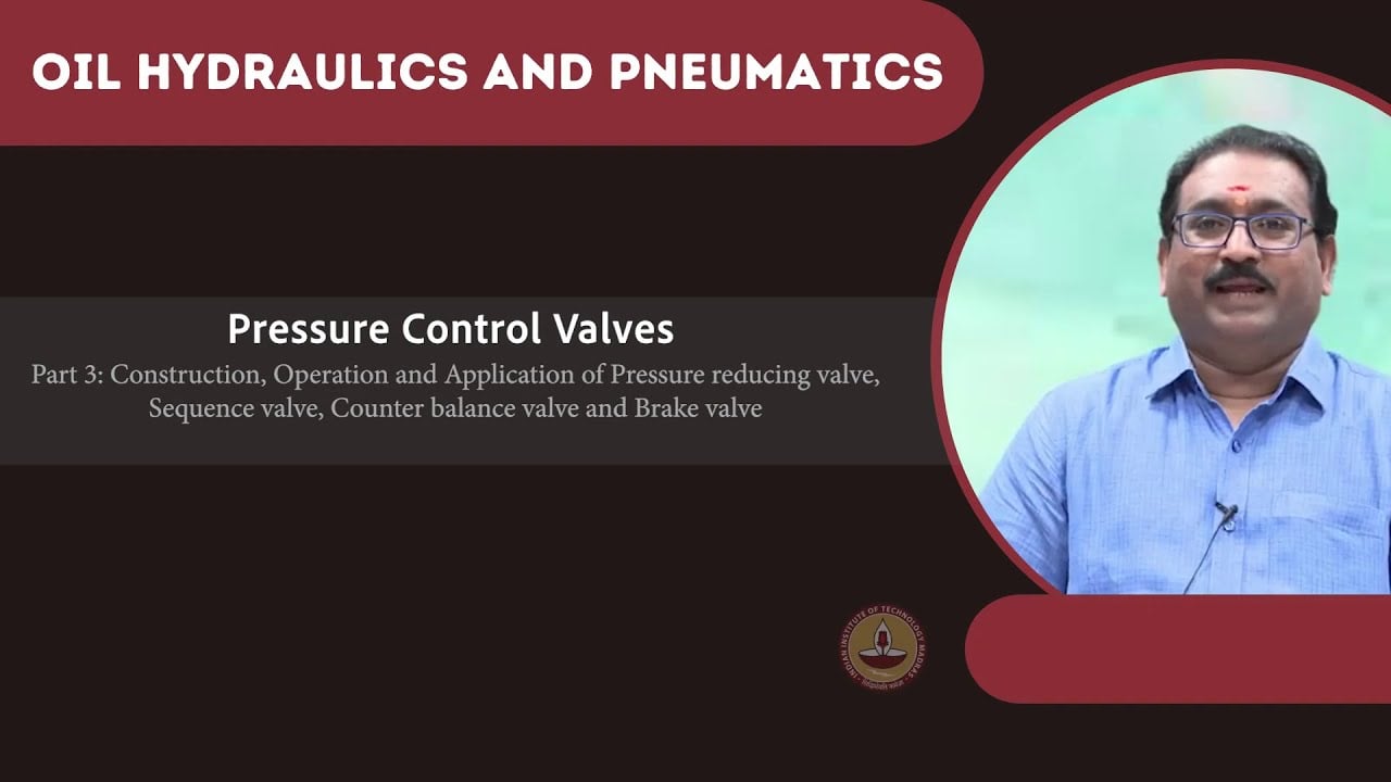
University lesson: operating principles
NPTEL-NOC IITM presents 5.8 – Pressure Control Valves. The lesson supports the valve operating principles used in the engineering discussion; it is not a model-specific repair, storage, or installation approval.