Wenzhou Prance Hydraulic Equipment Co., Ltd.

Radial Piston Motor Torque Ripple: Low-Speed Measurement and Diagnosis
Radial piston motor torque ripple is the variation of shaft torque over rotation, even when mean pressure and mean load appear steady. Piston engagement, distributor timing and the cam or crank geometry contribute to the pattern. At low speed, friction and load inertia can make the variation more visible as uneven motion. Diagnose it with time-linked pressure, speed and, where necessary, torque measurements. A low-speed wobble alone does not prove a defective motor. This guide explains what to measure, which alternative causes to exclude and what procurement evidence can support a smoother drive.
Mean torque does not describe every instant
The familiar displacement-and-pressure formula estimates mean theoretical torque. For displacement Vg in cubic centimetres per revolution and pressure difference delta-p in bar, mean ideal torque is approximately delta-p × Vg / (20pi) newton metres. Actual average torque depends on mechanical losses and the operating condition. This calculation does not establish the instantaneous torque waveform.
A radial piston unit develops force through several pistons acting against its reaction geometry. Their contributions change as the rotating assembly moves. The summed output can vary periodically. Different motor architectures use different piston arrangements, cam profiles and distribution systems, so a statement about one design should not be transferred to all radial piston motors.
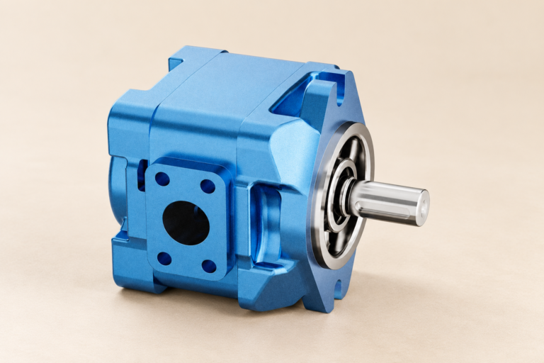
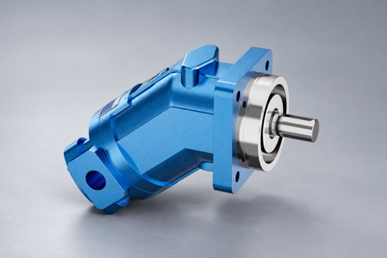
A multi-lobe cam, a crank-type arrangement and a motor with different active piston groups can have different relationships between shaft angle and torque. The catalogue's exterior photograph does not reveal all these internal features. Request design-specific information when the application's low-speed behaviour is critical.
Distinguish torque ripple from pressure ripple
Torque depends partly on the pressure difference acting across the motor. Pump delivery pulsation, valve switching, line dynamics or pressure-control behaviour can therefore influence shaft torque. A periodic pressure signal does not prove that the motor's geometric torque variation is the original source.
Measure motor inlet and outlet pressure where the approved test setup allows it. A pump gauge can miss pressure changes downstream of a valve or a long line. Return pressure matters because the motor operates on pressure difference, not simply inlet pressure. Use instruments with response suitable for the event being investigated.
Correlate the pressure record with speed and, if available, shaft angle or torque. A repeating pattern linked to motor rotation points to a different line of investigation from a pattern linked to pump speed or controller cycling. Several mechanisms can interact, so a correlation is useful evidence rather than final proof of a single cause.
Why low speed makes a problem easier to see
At low speed, the moving load may have less stored kinetic energy to smooth variations. Seal and bearing friction can become a larger part of the available torque, and static friction can differ from running friction. A drive may pause and restart even though a slowly updated gauge displays little change.
A heavy flywheel or gearbox may conceal motor torque variation during normal operation. Conversely, a compliant coupling, backlash or a frictional driven mechanism can amplify the visible speed pattern. A motor that behaves smoothly on an unloaded bench may therefore show irregular motion on a particular machine without an internal manufacturing fault.
Do not confuse minimum stable speed with the lowest speed at which any motion occurs. The application needs a definition of acceptable smoothness, load and observation interval. A specification that says only slow speed leaves purchasing and acceptance teams unable to distinguish an acceptable result from a problematic one.
Choose a practical measurement plan
Begin with speed and pressures, then add a torque transducer only if it is necessary to answer the question. A shaft torque sensor requires a suitable mechanical installation, alignment and protection. Its added inertia or compliance can influence the drive being studied, so the test arrangement must be reviewed as part of the method.
If speed is measured from pulses, specify the effective counts per revolution and acquisition method. A short counting window at very low speed may contain few counts, producing a coarse apparent variation. A longer window can hide the real variation. Pulse timing and a verified target can help, but missing pulses and target runout must still be excluded.
Use a common time base where possible. Record control command, load condition, temperature, inlet pressure, outlet pressure and speed together. Note the mechanical transmission and measurement location. A video of the machine can add event context but does not replace calibrated measurements of the quantities being evaluated.
A screening table for alternative causes
| Observed pattern | Possible contributor | Useful comparison |
|---|---|---|
| Variation repeats with shaft angle | Motor geometry, distribution or rotating damage | Shaft-angle-linked torque and pressure record |
| Variation follows pump speed | Pump delivery pulsation or shared hydraulic supply | Pump and motor frequency relationship |
| Stops followed by abrupt movement | Static friction, valve deadband or load stiction | Pressure build-up during each pause |
| Pattern changes with gearbox position | Transmission or driven-machine mechanics | Motor shaft versus final-drive speed |
| Reading changes with sensor setup | Target counting or acquisition error | Independent speed method and raw pulses |
Supporting technical context: NPTEL: hydraulic motor principles, NPTEL: hydraulic motor characteristics and low-speed operation. Illustrative calculations and qualitative checks do not establish a product rating or universal acceptance limit.
The table gives investigation routes rather than guaranteed diagnoses. It contains no universal allowable ripple percentage. Acceptance limits require a defined motor configuration, load, speed, temperature and measurement bandwidth.
Describe ripple with a clear definition
If torque is measured, state the mean, maximum, minimum and observation interval. A peak-to-peak percentage can be expressed as (Tmax minus Tmin) / Tmean × 100, provided the mean is nonzero and the chosen convention is explicit. Other suppliers may use a different definition or filtering, so compare methods before comparing numbers.
As an illustrative calculation, a record with a mean torque of 200 Nm, maximum 215 Nm and minimum 185 Nm has a peak-to-peak range of 30 Nm and a value of 15 percent under that definition. These are teaching values, not an acceptable limit or a product claim. The same raw record could yield a different reported result after different filtering.
For speed ripple, use an equally explicit definition. Avoid calling speed variation torque ripple unless torque is measured or the relationship is otherwise established. A drive's inertia and control system can substantially change the way torque variation appears in its speed trace.
Review operating conditions before selecting a repair
Check fluid temperature and viscosity requirements, contamination history, lubrication and the selected motor's permissible speed and pressure range. A cold-start condition can behave differently from a warmed production cycle. Comparing unmatched tests can lead to an unnecessary replacement or a false acceptance.
Review the valve controlling the motor. Poor low-flow resolution, deadband, hysteresis or an unstable command can make a motor accelerate unevenly. A proportional control system may require a suitable tuning review. Do not change dither, current limits or compensation settings outside the manufacturer's and machine designer's approved procedure.
Inspect the mechanical load under isolation. Misalignment, bearing defects, binding, intermittent contact or excessive backlash can create cyclic resistance. If irregularity occurs only at one machine position, that evidence is valuable. A motor test should be planned to distinguish the hydraulic component from the driven equipment without introducing unsafe unloaded motion.
Procurement questions for a smooth low-speed drive
State the required loaded speed range and the acceptable motion variation. Include start, stop, reversal and dwell requirements. Describe load torque, inertia, gearbox ratio, coupling and any brake. Specify whether the machine relies on feedback control or open-loop flow regulation. These requirements are more useful than requesting a motor with low ripple without defining the task.
Ask for performance evidence at relevant conditions. A rated maximum torque figure does not answer a low-speed smoothness question. Request the measurement method, filtering, load and temperature behind any ripple or minimum-speed claim. If catalogue data are unavailable, define a practical acceptance test with the supplier.
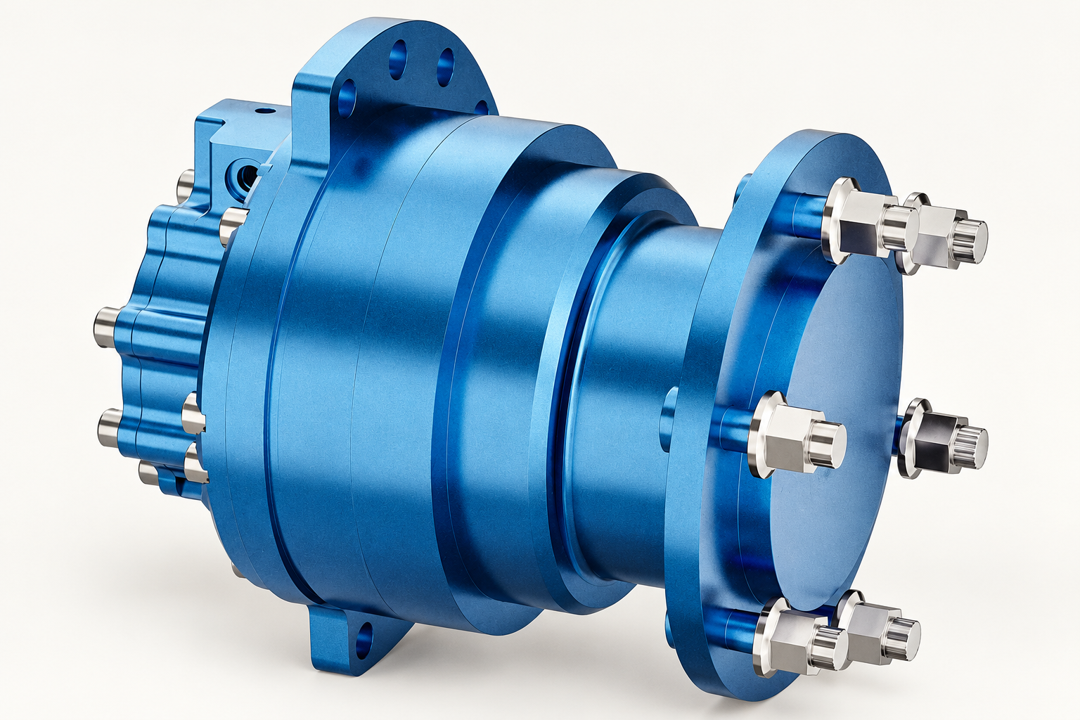
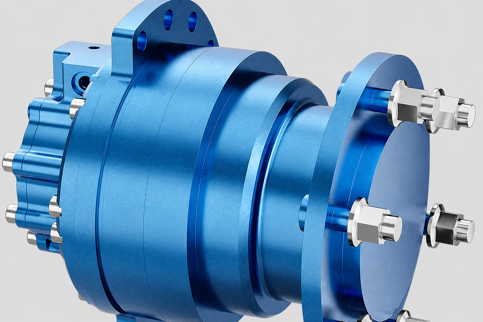
Prance's MCR radial piston motor is a relevant family for a low-speed drive enquiry. Its reference-based illustrations show the exterior housing and connections. They do not reveal a measured torque waveform, number of effective torque cycles or guaranteed minimum stable speed. Confirm the exact ordered configuration and test evidence before using such figures in a machine specification.
Decide what the evidence supports
A repeatable fluctuation measured under controlled conditions can justify further investigation. It does not necessarily justify replacing the motor. Compare an approved alternative operating point, matched temperature conditions or a verified control setting where the test plan allows it. Change one variable at a time so the result remains interpretable.
If a component is removed for workshop review, retain the field records. The bench team needs to know which speed, load and event produced the problem. A general report that the motor was jerky may result in a normal high-speed test that misses the actual issue.
Close the investigation with a specific conclusion: instrument error corrected, control behaviour improved, mechanical binding removed or a component defect confirmed by defined evidence. If uncertainty remains, state it and identify the next discriminating measurement. Avoid presenting an unmeasured assumption as a verified root cause.
Häufig gestellte Fragen
Do all radial piston motors have identical torque ripple?
No. Internal architecture, piston arrangement, distribution and operating conditions differ. Obtain evidence for the exact configuration and compare tests using the same definition and measurement method.
Can I diagnose torque ripple using only a pressure gauge?
A gauge provides pressure information at its test point. It does not directly measure shaft torque, and a damped display can hide dynamics. Correlate appropriate pressure, speed and, where required, torque records.
Why is rotation uneven only at very low speed?
Low inertia, friction, control resolution and motor torque variation can all contribute. Record the loaded condition and exclude sensor and mechanical effects before attributing the symptom to an internal motor defect.
Is a quoted ripple percentage enough for purchasing?
No. Ask for the definition, load, speed, temperature, filtering and test setup. Percentages calculated differently cannot be compared reliably, and a high-speed result may not answer a low-speed application question.
Will a larger motor automatically make the drive smoother?
Not necessarily. Displacement changes torque and flow requirements, but control behaviour, friction, inertia and architecture still matter. Evaluate the complete duty and verify relevant low-speed performance.
Related products and engineering guides
Radialkolbenmotor MCR, related hydraulic product range, Radialkolbenmotor – Funktionsprinzip: Drehmoment bei niedriger Drehzahl, Minimale Drehgeschwindigkeit des Hydraulikmotors: Stiftverschleiß und glatte Rotation, Fehlfunktion des Hydraulikmotors: Symptome und Ursachen. Provide the circuit, fluid, duty and exact ordered configuration when requesting component-specific data.
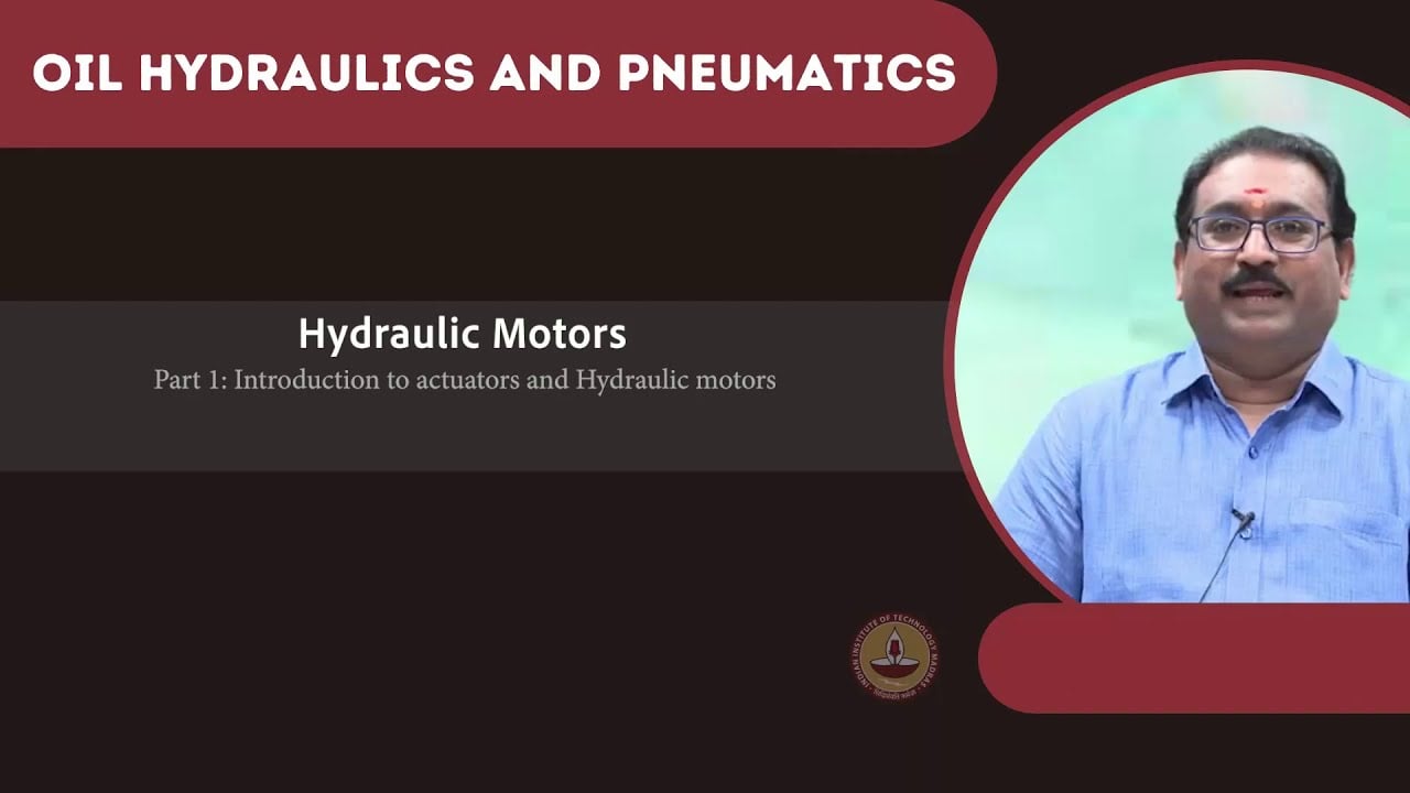
University lesson: 6.3 – Hydraulic Motors
This NPTEL university lecture explains the component principles underlying this guide; the lecture is background education rather than a configuration-specific test procedure.
Technical references
- NPTEL: hydraulic motor principles
- NPTEL: hydraulic motor characteristics and low-speed operation
- NIOSH: hazardous-energy isolation
Sources support the stated principles and method scope. Illustrative inputs and another manufacturer’s documents do not establish Prance component ratings, warranties or brand affiliation.