Wenzhou Prance Hydraulic Equipment Co., Ltd.

Hydraulic Wheel Motors with Brakes: Drive and Parking-Brake Requirements
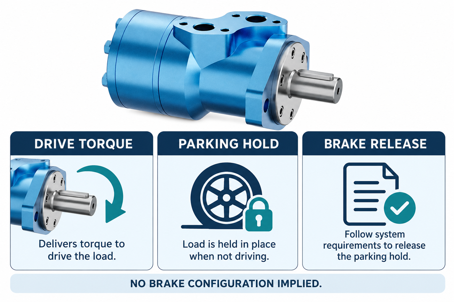
Integrating a hydraulic wheel motor with braking requires separate decisions about wheel-drive torque, controlled stopping, parking hold, and brake release. A motor that can propel the wheel does not automatically hold a parked machine, and a brake rated to hold a stationary load is not automatically suitable for repeated dynamic stopping. Verify the complete mechanical load path and the hydraulic or electrical control arrangement for the actual machine. Do not infer an integrated brake from a wheel-motor product name or exterior photograph.
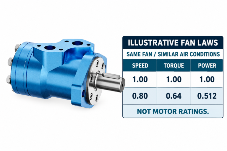
The BMR catalog motor in the illustrations is a real exterior reference for the drive component. The images deliberately do not show an invented brake housing or claim that the pictured configuration includes a particular brake. This guide addresses system requirements, not approval of a named motor-brake combination.
Define the functions before comparing assemblies
Wheel drive supplies motion and traction. Service braking manages the moving machine’s deceleration under the intended operating conditions. Parking hold keeps the stationary machine from unintended movement. Emergency or secondary behavior may introduce additional requirements defined for the actual equipment and its applicable design framework.
These functions can share components in a verified design, but shared hardware does not erase their different duties. A hydraulic drive that slows a moving machine is not automatically a parking system after pressure is lost. Likewise, a mechanically holding brake should not be assumed capable of absorbing repeated stopping energy merely because it has enough stated static torque. Define the required functions first, then assess how the proposed architecture satisfies each.
Establish the wheel and drivetrain load path
Record where torque travels between the motor, coupling or gearing, brake, wheel, axle support, and machine frame. A brake mounted upstream of a transmission holds through that transmission only while the relevant mechanical path remains intact and behaves as assumed. A wheel-mounted arrangement can present a different load path and installation problem.
Use the actual drawings and mechanical ratings. Do not assume that a matching shaft connection establishes allowable radial or axial loading, wheel offset, fastener suitability, or structural integrity. The motor’s drive capability and its support capability are separate questions. If the wheel is supported independently, show that arrangement clearly so neither the supplier nor installer assumes the motor bearings carry loads that the design intended another component to carry.
Keep propulsion torque separate from parking torque
Propulsion demand can include grade, rolling resistance, acceleration, and other loads under the intended operating conditions. Parking hold addresses a stationary condition, including the relevant slope and external loads. Both requirements need the actual wheel radius and transmission arrangement, but they are not the same calculation or acceptance test.
For a simplified static concept, the downslope component of weight is m × g × sin(θ), and the corresponding total wheel torque associated with that component is that force multiplied by effective wheel radius. This is not a brake selection formula by itself. Load distribution, available tire-ground contact, gearing, mechanical efficiency, wear, adverse conditions, design margins, and the applicable machine requirements still need assessment by the responsible designer.
Identify what the brake rating actually describes
Obtain the brake’s exact documentation and determine whether a stated value concerns static holding, dynamic stopping, another condition, or a particular test. Temperature, wear, engagement conditions, lubrication where relevant, and operating duty can affect the interpretation. A single torque number without its conditions is an incomplete specification.
If dynamic stopping is intended, the energy and repetition of those events matter as well as peak torque. A device that can hold an already stationary shaft may not be approved to stop it from operating speed. Keep rated capability separate from an illustrative engineering calculation and from observations during a limited prototype test. The complete operating envelope must be assessed rather than inferred from one favorable value.
Use a system-function matrix
| Funktion | Inputs that matter | Evidence required from the proposed design |
|---|---|---|
| Wheel propulsion | Speed, traction demand, grade, acceleration, and hydraulic supply | Motor and drivetrain capability over the required duty |
| Controlled stopping | Moving mass, speed, inertia, stop profile, and repetition | Suitable braking architecture and verified dynamic duty |
| Parking hold | Stationary load, slope, contact conditions, and load path | Holding capability in the intended parked state |
| Brake release | Selected brake mechanism and control conditions | Approved release method and confirmation of usable clearance |
| Loss or change of energy supply | Hydraulic, electrical, and mechanical system states | Defined behavior and appropriate machine-level validation |
| Service and recovery | Isolation, support, access, and approved maintenance method | Safe procedures that do not bypass a required holding function |
The matrix is an application-review tool. It does not establish the safety category, brake rating, or approved control architecture for a particular machine.
Review release conditions for the selected mechanism
Some brake designs use hydraulic pressure for release, while others use different mechanisms. If a pressure-released design is selected, confirm the required release conditions, connection arrangement, permitted pressure, relevant return or drain requirements, and the effect of pressure changes. Do not adopt a generic release-pressure value from another brake.
The control sequence must account for the actual mechanical and hydraulic response. Developing drive torque against a brake that has not released properly can create heat or damage, while releasing a holding function without appropriate control of the machine can permit unintended movement. Specify how readiness is established and validated. This article does not provide a universal sequence that may be applied to an unidentified motor-brake assembly.
Do not confuse hydraulic load control with parking hold
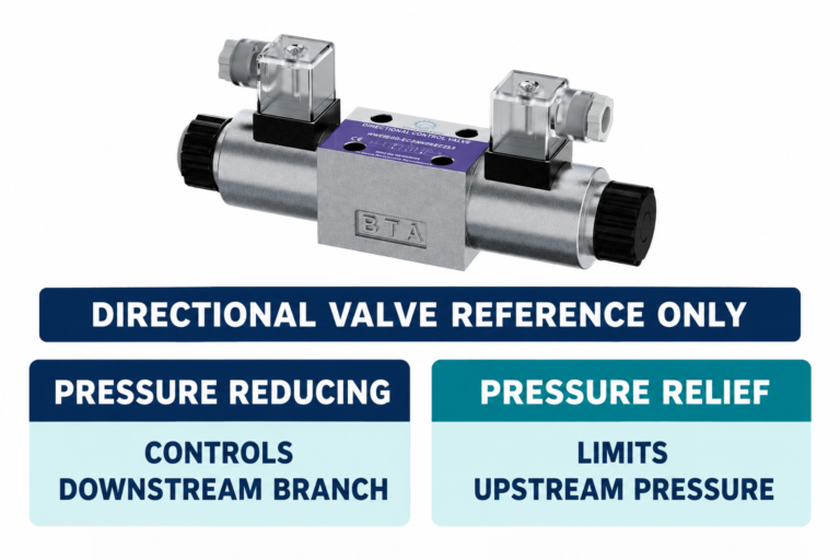
A load-control or counterbalance arrangement can influence an overhauling load during movement, and relief or anti-cavitation arrangements can address other circuit conditions. Their presence does not by itself prove that the complete machine will remain securely parked under every intended condition after power is removed.
Review internal leakage, pressure decay, isolation, external forces, and the actual mechanical holding arrangement as part of the system design. Do not treat a closed directional valve or an apparently steady pressure gauge as the whole parking assessment. The purpose is not to dismiss a verified hydraulic function, but to avoid assigning it an additional holding duty that has not been defined and demonstrated for the machine.
Include operating states and transitions
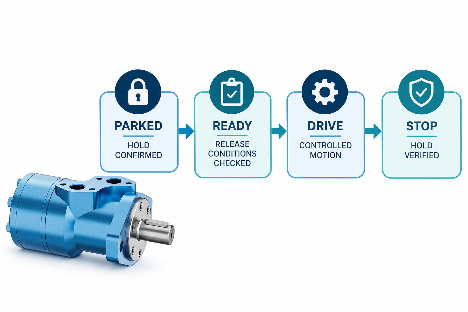
A useful integration review considers parked, preparing to move, driving, stopping, and returning to the parked state. It also identifies relevant changes of supply, command, load, and machine attitude. The transition between states can be as important as steady operation, particularly where one function depends on another having reached a verified condition.
Use the approved control design and the applicable machine requirements to determine how those states are managed. A conceptual state chart is a planning aid, not executable control logic. Do not infer release timing, interlocks, diagnostic coverage, or failure behavior from the drawing in this article. Those details require appropriate engineering and validation for the actual equipment.
Check fluid, temperature, and auxiliary interfaces
A combined or adjacent brake arrangement can introduce fluid and interface questions beyond the motor’s main supply and return. Determine the required fluid or lubrication conditions, separation between compartments where applicable, temperature limits, and auxiliary connections. A shared mounting location does not establish compatibility between fluids or allow unrelated passages to be connected.
Retain complete identities for the motor, brake, connectors, and any control or feedback equipment. Confirm physical access and the ability to inspect or service the assembly under the approved procedure. When a supplier proposes another configuration, review the changed interfaces and operating requirements rather than treating it as an equivalent solely because its main shaft and mounting pattern resemble the original.
Make the enquiry specific enough to review
Provide machine duty, moving and parked loads, wheel dimensions, speeds, slope requirements, stop behavior, operating temperature, hydraulic supply, intended control architecture, and the mechanical drawing. Identify which party is responsible for motor supply, brake selection, transmission design, controls, and final machine validation.
Ask the provider to state what its product data proves and what remains outside its scope. A catalog motor quotation is not automatically approval of the complete vehicle braking system. If a configured motor-brake assembly is offered, request its complete identity, relevant ratings and conditions, installation requirements, and supporting test information. Keep assumptions visible rather than allowing an ambiguous description to become an unverified integration claim.
Verify the complete machine through competent procedures
Testing a wheeled machine requires appropriate restraint, exclusion of people from hazardous movement, and approved procedures. Do not demonstrate parking capability by improvising a slope test or defeating a release mechanism. HSE workplace-transport guidance emphasizes preventing unintended vehicle movement; actual design and verification must suit the equipment and operating environment.
Retain the approved test plan, relevant load and environmental conditions, installed identities, observations, and results. Verify the required propulsion, stopping, holding, and transition behavior rather than accepting a successful unloaded rotation as proof of braking performance. Record limitations of the test and the conditions that were not reproduced so later users do not extend a narrow result beyond its demonstrated boundary.
Häufig gestellte Fragen
Does a wheel motor automatically include a parking brake?
No. Confirm the exact supplied configuration and its documentation. The BMR exterior shown here is not evidence of an integrated brake or a particular holding rating. A product name alone cannot establish the complete braking architecture.
Can static holding torque be used as a dynamic stopping rating?
Not without specific approval. Static holding and dynamic stopping involve different conditions, including energy and repeated duty. Use the brake’s documented ratings and the complete machine review.
Will closing the directional valve keep the machine parked?
That is not a sufficient general conclusion. Leakage, pressure changes, external loads, and the actual holding arrangement must be considered. Verify the intended parking function at machine level rather than relying on one valve state.
Is brake release pressure the same for all motor-brake assemblies?
No. It depends on the selected brake and its operating requirements. Confirm the applicable values, connections, and control conditions from the exact documentation. Do not borrow settings from a similar-looking assembly.
What should a supplier confirm before an order is placed?
The supplier should identify the exact configuration, relevant capability and conditions, mechanical and fluid interfaces, installation requirements, and the limits of its supplied scope. The machine designer must still resolve integration and validation responsibilities.
Produktdaten und entsprechende technische Ressourcen
The Hydraulic Wheel Orbit Motor BMR catalog exterior is used as the real product reference in these explanatory images. It does not establish the approved service method, optional construction, or operating limits for an individual order. Confirm the complete code and its documentation. Related resources: Hydraulischer Rad-Gerinomotor BMR, Hydraulikmotor-Palette, Hydraulic Wheel Orbit Motor: Applications & Selection Guide, Hydraulic Motor Brake Release Pressure: Setup and Testing, Hydraulikmotor-Senkbremsventil: Steuerung von überlaufenden Lasten.
Sources and limits of this guide
The university resource supports the component operating principles. NIOSH supplies hazardous-energy prevention context; exact machine isolation and component service requirements still need their approved procedures. Sources explain general operating principles, not performance ratings or optional features of the pictured catalog component.
- NPTEL: Grundlagen der industriellen Ölhydraulik und Pneumatik
- NIOSH: Verletzungen durch gefährliche Energie verhindern
- HSE: workplace transport parking and immobilisation
University lesson: operating principles
NPTEL-NOC IITM presents 6.3 – Hydraulic Motors. The lesson supports the motor operating principles used in the engineering discussion; it is not a model-specific repair, storage, or installation approval.