Wenzhou Prance Hydraulic Equipment Co., Ltd.

Pressure-Reducing vs Relief Valves: Downstream Control and System Limits
A pressure-reducing valve regulates a lower pressure in a downstream branch, while a pressure-relief valve opens a discharge path when the pressure it senses reaches its operating threshold. They solve different problems and cannot be substituted merely because both have a pressure adjustment. In a basic arrangement, the reducing valve meters flow in series with the branch and senses downstream pressure; the relief valve connects a protected pressure region to a discharge path and responds to upstream pressure. Actual pilot-operated and combined designs must be identified from their own symbols and documentation.
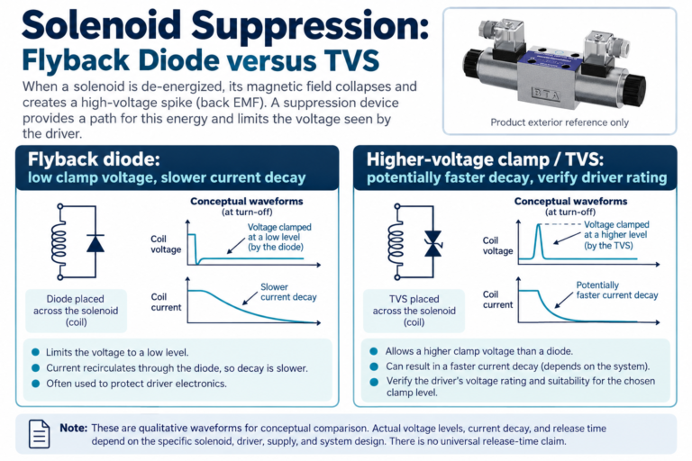
The pictured 4WE is a directional-valve exterior reference for the surrounding hydraulic system. It is not presented as a pressure-reducing or relief valve, and the explanatory graphics are not approved installation drawings.
Begin with the pressure region that needs control
Ask whether the requirement is a lower operating pressure in one part of the machine or an upper pressure boundary for a particular region. A clamping branch might need a lower working pressure while another branch uses the main supply at a higher pressure. That is a different task from providing a path for pump flow when the system reaches its intended pressure limit.
Draw the relevant supply, branch, load, and return paths and identify where pressure is sensed. A component cannot control a pressure region simply because it is installed somewhere in the same machine. Isolation by another valve, an external load, or a different circuit state can change which region a particular pressure-control element can influence.
Understand how a basic reducing valve behaves
A basic pressure-reducing valve is commonly described as normally open: it permits passage while the downstream pressure is below the condition that causes regulation. As the sensed downstream pressure rises, its metering element reduces the opening to regulate that branch. The available supply pressure and the valve’s operating requirements still matter.
This does not mean the valve creates pressure independently of the supply or load. It needs suitable upstream conditions and cannot maintain a requested downstream pressure when the necessary supply is absent. Flow demand, pressure drop, regulation characteristics, and the specific design affect actual operation. Use the documented performance curves and applicable operating conditions rather than treating the adjustment scale as a guarantee of identical pressure at every flow.
Understand how a basic relief valve behaves
A basic relief valve is commonly described as normally closed until the sensed pressure produces the condition for opening against its controlling forces. It then permits flow through the discharge path. The relationship between pressure and relieved flow depends on the design; the pressure at first opening and the pressure while passing substantial flow need not be identical.
The discharge route is part of the function. Return pressure, backpressure, pilot or drain arrangements, and plumbing can affect the selected valve’s behavior. A relief element with an unsuitable return path is not adequately specified by its adjustment alone. Identify the protected region, required flow, applicable pressure characteristics, and the conditions in all relevant machine states.
Compare the functions directly
| Comparison | Basic pressure-reducing task | Basic pressure-relief task |
|---|---|---|
| Main objective | Regulate a lower downstream branch pressure | Limit a sensed upstream pressure by providing discharge flow |
| Typical location | In series with the regulated supply branch | In a discharge path from the protected pressure region |
| Pressure feedback | Downstream branch condition | Upstream protected-region condition |
| Simplified normal state | Open before downstream regulation is needed | Closed before the relief opening condition is reached |
| Important performance question | Pressure regulation over required branch flow | Pressure versus relieved flow and discharge conditions |
| Common mistaken assumption | It can release every pressure increase downstream | It establishes any desired lower branch operating pressure |
These comparisons explain simple functions. Combined, pilot-operated, reverse-flow, or externally drained arrangements must be reviewed using their own circuit information.
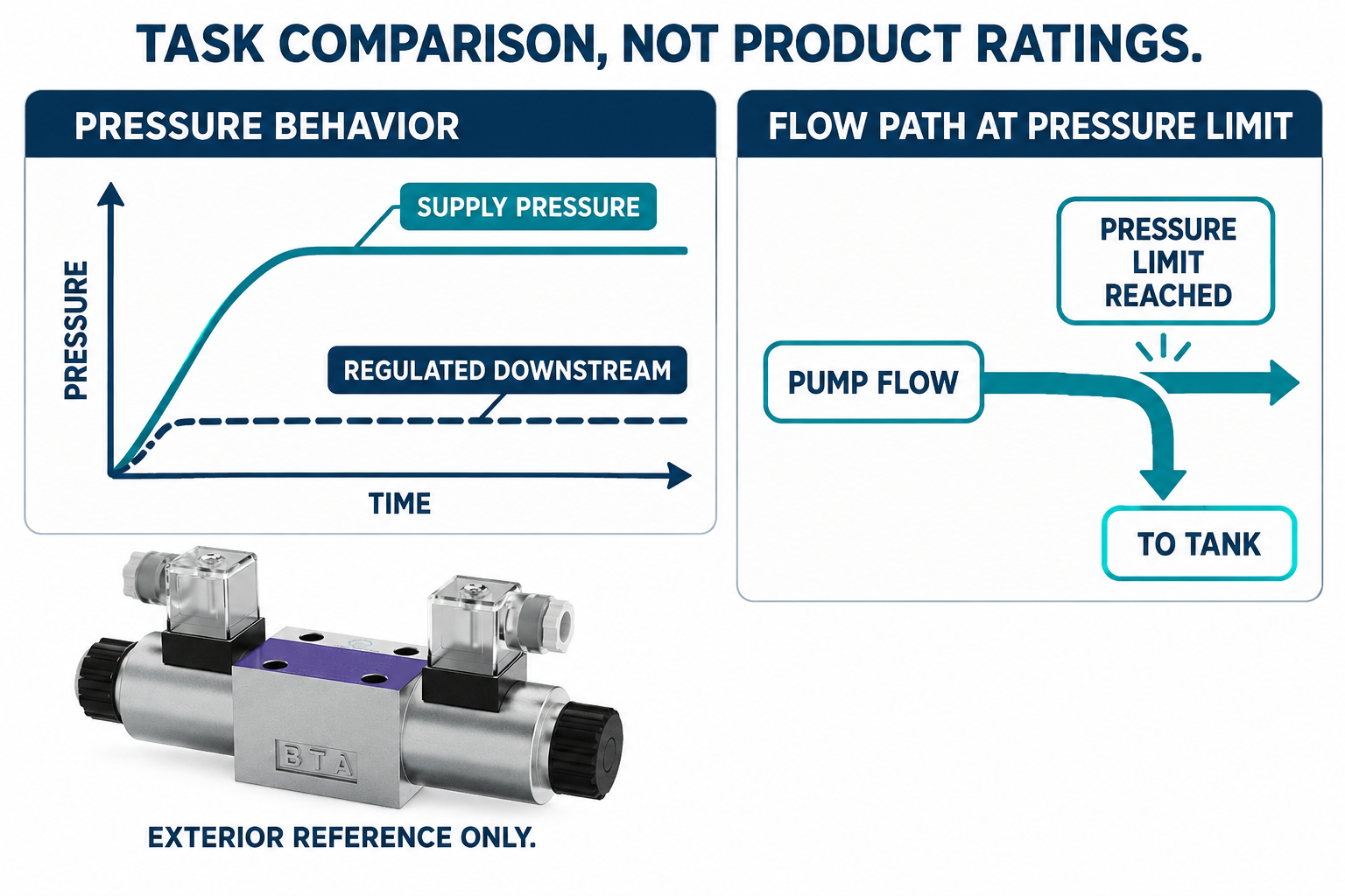
Do not use a relief valve as a direct replacement for branch regulation
A relief valve connected from a branch to tank can discharge flow above a pressure-related condition, but that is not automatically equivalent to placing a reducing valve in series with a branch supplied from a higher-pressure system. The flow paths, operating states, energy losses, and interactions with the main circuit differ.
If a branch needs controlled lower-pressure supply while other functions continue operating, review a suitable pressure-regulating arrangement rather than selecting whichever adjustable valve is cheapest or already available. Identify what happens when the branch is moving, stopped, isolated, or driven by an external force. The complete circuit must provide the intended behavior; a shared pressure setting does not make two different functions interchangeable.
Recognize the limits of a two-way reducing function
A reducing valve that meters incoming supply is not necessarily able to discharge a pressure rise generated on its downstream side. An external load, trapped-fluid heating, or another source may raise pressure in a region that closing the inlet does not relieve. Do not assume that the word reducing guarantees protection against every downstream event.
Determine whether the design includes a relieving function, another discharge path, or additional protection suitable for that region. Review the exact symbol and operating description. This distinction should be made before selecting parts, especially where another valve can isolate the load. It is a function-identification issue, not a recommendation to add an unreviewed bypass or adjustment in an existing machine.
Evaluate heat where pressure is intentionally dropped
When fluid passes through a pressure drop, hydraulic power is dissipated. Using bar and liters per minute, the power associated with a pressure drop is approximately Δp × Q / 600 in kilowatts. This is a unit-converted hydraulic relationship, not a model rating or a complete estimate of the machine’s heat balance.
For an illustrative branch with a 100-bar pressure drop and 12 L/min passing through that drop, the associated hydraulic power is 100 × 12 / 600 = 2 kW. These assumed values explain the calculation only. Actual heat generation depends on the real flow, pressure, duty cycle, and circuit states. Assess whether the architecture unnecessarily maintains a high supply pressure for a large lower-pressure demand, rather than treating regulation as energy-free.
Select from required flow as well as pressure
The reducing valve must regulate over the branch’s relevant flow range, while the relief arrangement must handle the required discharge condition. Review performance data at appropriate fluid and temperature conditions, including the effects of pressure loss and response. A maximum catalog flow description may use different conditions from those that matter in the machine.
Keep continuous operation, short transients, and unusual operating states distinct. Specify the expected branch demand and the pressure region to be controlled, then check the required supply and return conditions. Avoid selecting solely from port thread or a maximum pressure label. Mechanical connection compatibility is necessary, but it does not demonstrate useful regulation or adequate discharge performance.
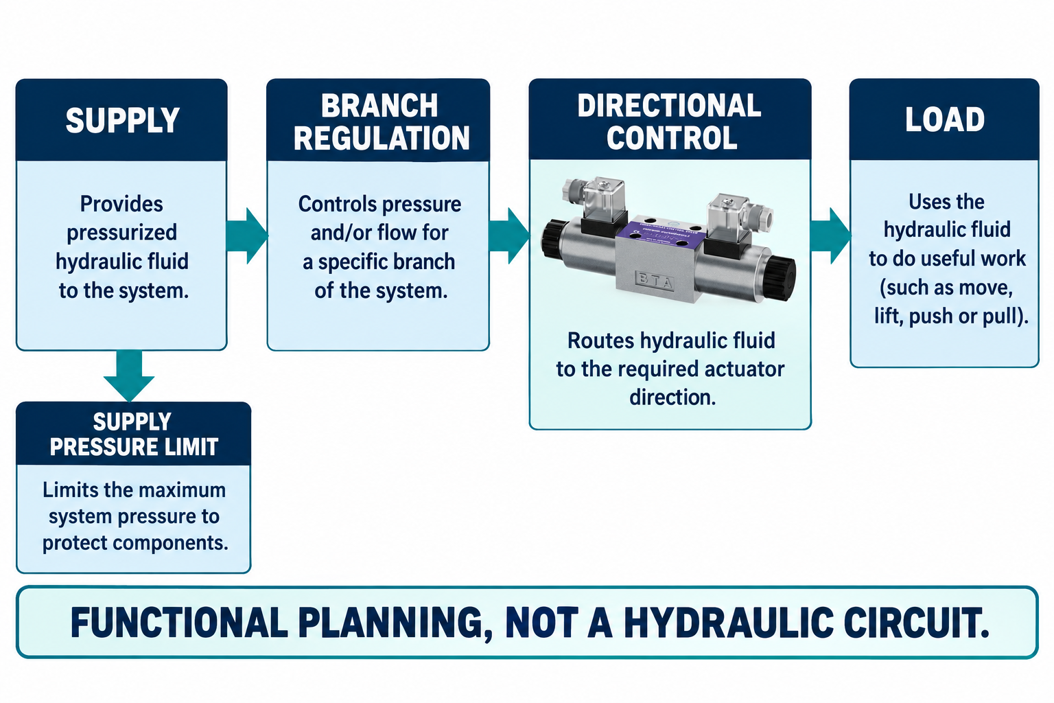
Identify pilot, drain, and reverse-flow arrangements
Some designs include pilot stages, drain connections, reverse-flow provisions, or other options that change installation requirements. Do not infer those features from an external adjustment screw or a familiar housing shape. Record the complete code and the applicable symbol, then review every connection and operating position.
Pressure in a pilot or drain line can be relevant to the intended function. A connection that appears convenient in the manifold may not meet the selected valve’s requirements. Likewise, an actuator that needs reverse movement may require an approved path that differs from the forward reducing function. Resolve these questions in the circuit design rather than assuming oil can always travel backward through a pressure-control element without consequence.
Measure the conditions that distinguish the two tasks
For a reducing function, useful evidence identifies supply pressure, regulated downstream pressure, branch flow, and the state of the load. For a relief function, useful evidence identifies pressure at the protected region, discharged flow where required, and the relevant return or drain conditions. Record temperature and the measurement locations.
An upstream gauge alone cannot establish the regulated pressure at a remote branch with intervening losses or isolation. Similarly, a momentary pressure indication does not describe the pressure-flow behavior of a relief valve. Use suitable instruments and approved test points with competent personnel. Do not change settings repeatedly to diagnose an unidentified function or attempt to measure a dangerous transient through an improvised connection.
Verify the complete machine after selection or service
Use the approved isolation, pressure-release, load-restraint, installation, and commissioning procedures. Stopping the pump does not guarantee that every hydraulic region is free from pressure, and a closed valve can leave energy trapped elsewhere. Define the relevant operating states and the observations that require stopping before the machine is energized.
Verify the intended branch pressure and the protected-region behavior under the required duty, including interactions with other functions. Retain the valve identities, final settings under the applicable procedure, measurement conditions, and test results. Where the complete duty could not be reproduced, record the remaining limitation instead of treating one stable gauge reading as proof of every circuit state.
Häufig gestellte Fragen
Can a reducing valve replace the main relief valve?
Not simply because their adjustment ranges overlap. Their usual pressure regions and flow paths differ. Identify the required protective and regulating functions from the complete circuit, then select the appropriate arrangement for each.
Does a reducing valve always release high downstream pressure?
No. A basic incoming-flow regulating function does not necessarily provide a discharge path for pressure generated downstream. Check whether the actual design has a relieving function or whether another approved arrangement handles that condition.
Are all reducing valves normally open and all relief valves normally closed?
Those descriptions explain common simple functions. Actual combined and pilot-operated designs can require more detailed interpretation. Use the specific symbol and operating documentation rather than applying a simplified label to an unidentified assembly.
Why can a lower-pressure branch still generate heat?
Fluid passing through a pressure drop dissipates hydraulic power. The amount depends on pressure difference, flow, and operating duration. Evaluate actual circuit states and losses rather than assuming that reducing pressure automatically saves the same amount of input energy.
What should be included in a pressure-control enquiry?
Provide the circuit and pressure regions, supply and branch requirements, relevant flow range, fluid and temperature conditions, return and drain arrangement, operating states, and required performance evidence. The actual function must be clear before a part can be selected responsibly.
Produktdaten und entsprechende technische Ressourcen
The Directional Valve 4WE catalog exterior is used as the real product reference in these explanatory images. It does not establish the approved service method, optional construction, or operating limits for an individual order. Confirm the complete code and its documentation. Related resources: Wegeventil 4WE, Hydraulikventilpalette, Wie man eine Frage zur Einstellung eines Hydraulikdruckbegrenzungsventils für eine Schaltungsprüfung vorbereitet, Wie sollten Systemplaner den Druckverlust von Hydraulikventilen interpretieren?, Wann sollte ein Käufer ein direktgesteuertes oder ein vorgesteuertes Ventil wählen?.
Sources and limits of this guide
The university resource supports the component operating principles. NIOSH supplies hazardous-energy prevention context; exact machine isolation and component service requirements still need their approved procedures. Sources explain general operating principles, not performance ratings or optional features of the pictured catalog component.
- NPTEL: pressure relief principles
- NPTEL: pressure reducing valve principles
- NIOSH: Verletzungen durch gefährliche Energie verhindern
University lesson: operating principles
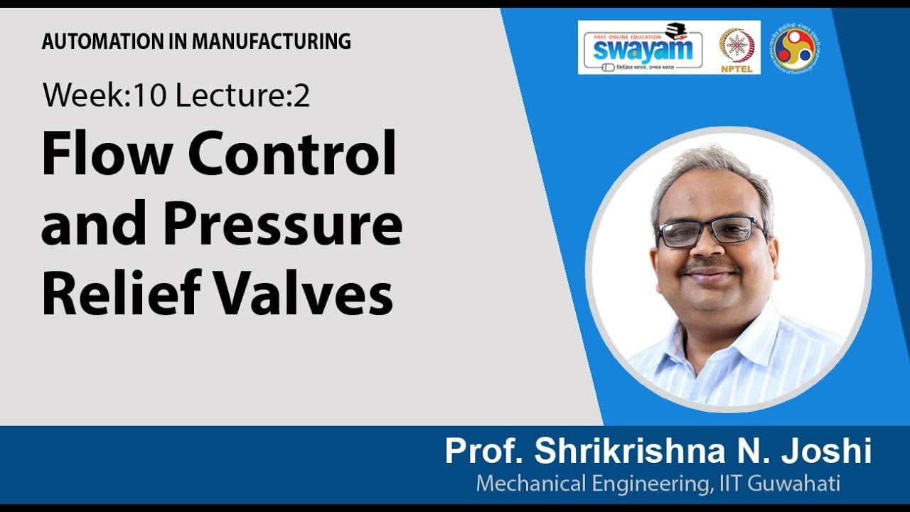
NPTEL IIT Guwahati presents Lec 31: Flow control and pressure relief valves. The lesson supports the valve operating principles used in the engineering discussion; it is not a model-specific repair, storage, or installation approval.