Wenzhou Prance Hydraulic Equipment Co., Ltd.

Measuring Proportional Valve Hysteresis: Rising and Falling Command Curves
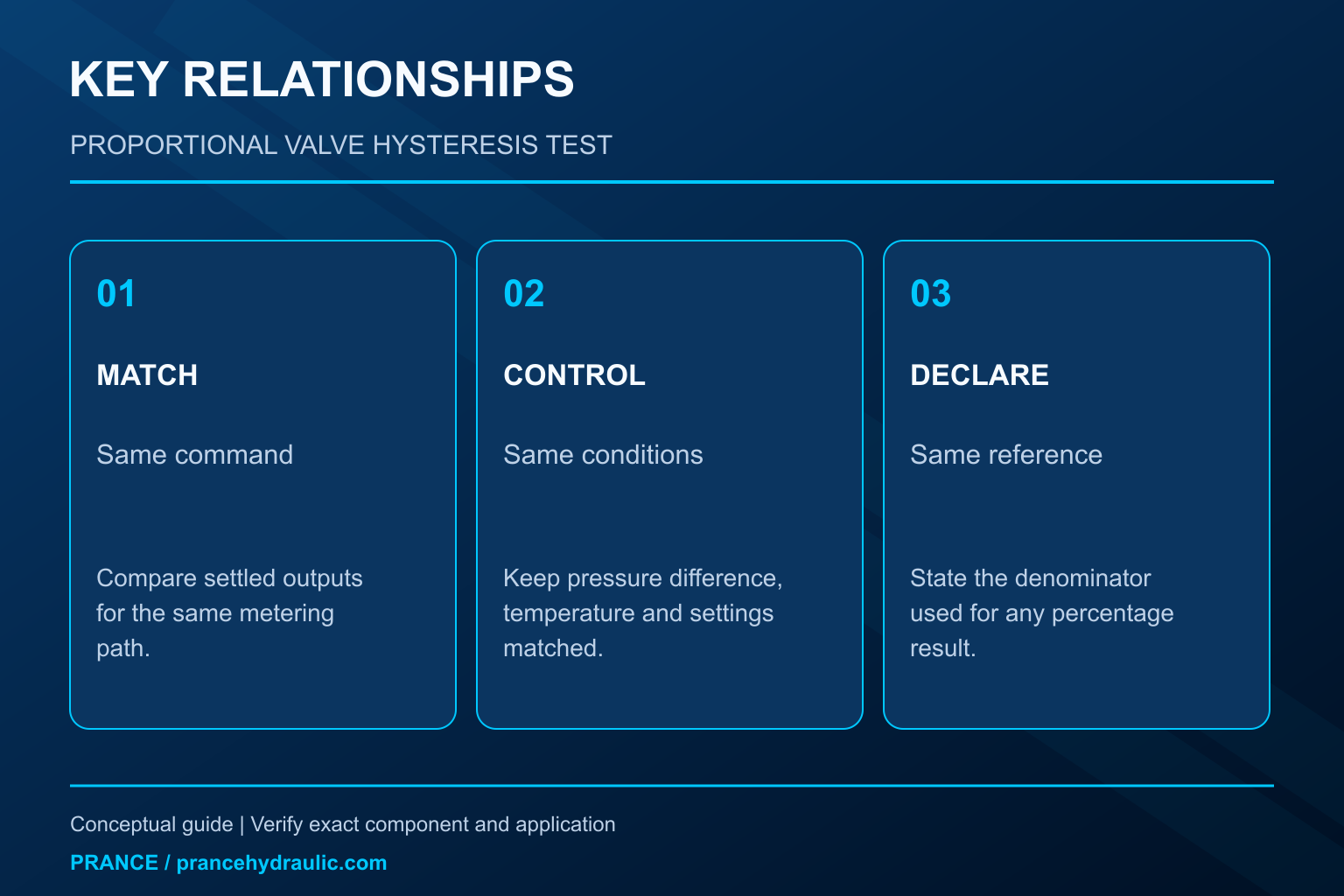
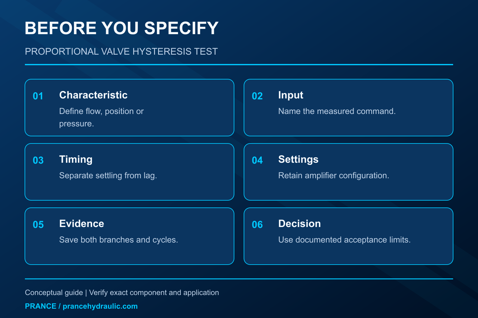
Proportional valve hysteresis measurement compares the output reached while command increases with the output reached while command decreases, under matched conditions. For a hydraulic flow-control assessment, record both flow-versus-command branches at a controlled pressure difference and fluid temperature. Keep the input definition, amplifier settings, sweep rate, and normalization explicit. A loop produced by changing pressure, insufficient settling, or sensor delay is not automatically the valve’s static hysteresis. This guide explains a practical measurement and interpretation framework, rather than replacing the selected valve’s approved test method.
Define the characteristic before planning the test
Decide whether the output of interest is spool position, flow, or controlled pressure. These are related but different characteristics. A valve with spool feedback may position its spool repeatably while delivered flow changes with pressure difference. A flow-versus-command loop therefore describes the complete tested hydraulic and electrical arrangement unless the method isolates other effects.
Define the input equally carefully. Controller command voltage, amplifier demand, measured coil current, and a normalized digital setpoint are not interchangeable. Record the actual input to the characteristic being assessed. If the amplifier applies deadband compensation, ramps, current regulation, or other shaping, the measured response includes those settings.
The research on pilot-operated proportional directional valves linked below records complete input cycles and corresponding flow to assess static behavior. It supports the need to state the tested path and conditions. Its reported results belong to its experimental valve and apparatus; they are not a performance claim for a Prance valve or a universal acceptance threshold.
Use one controlled comparison for each metering path
For a directional valve, identify the tested port pair and direction. Supply-to-work and work-to-return edges can have different geometry and pressure conditions. Compare ascending and descending data for the same path before comparing different paths. Combining several edges into one curve can hide which condition produced the separation.
Pressure difference across the metering path must be controlled or recorded closely enough to interpret flow. Under the usual simplified turbulent-orifice model, flow depends on opening area and the square root of pressure difference. A pressure change can therefore move the flow curve even if the spool returns to the same position. The model has limits, especially near very small openings or changing fluid conditions.
Control inlet fluid temperature and document viscosity or the fluid specification. Temperature can influence hydraulic losses and electrical behavior. A rising sweep taken with cold oil and a falling sweep taken after substantial warming do not form a clean direction-only comparison. Stabilize the apparatus as required by the approved method before recording the comparison.
Separate quasi-static hysteresis from dynamic lag
A static-characteristic test changes command slowly enough, or waits at defined steps long enough, to obtain the required settled response. A dynamic test intentionally examines response over time or frequency. Both are useful, but their loop widths should not be compared as though they measure the same property.
If the command changes faster than the valve or measuring system can follow, output lag creates a loop. Reducing the sweep rate and checking convergence can help distinguish this contribution. The test method must define settling and valid sampling criteria; a visually smooth curve is not evidence that settling occurred.
Signal filtering adds another delay. Record the flow sensor’s response, data acquisition settings, and amplifier filtering where available. Use synchronized timestamps and compare channels on the same time basis. A delay between the logged command and flow channels can create an apparent separation even when the underlying steady-state relationship is repeatable.
Keep the amplifier configuration visible
Document current limits, offset, gain, ramp settings, dither settings, and any active feedback. Dither can influence friction-related behavior, but changing it also changes the tested configuration. Do not tune it during one branch and retain the other branch as though they belong to a single controlled test.
Use the manufacturer’s permitted electrical interface and test procedure. Do not guess a pinout, apply an assumed voltage to a feedback terminal, or disable protection to simplify measurement. A valve’s external connector appearance does not establish its command range, supply requirements, or signal reference.
For a position-feedback valve, retain the feedback trace if the approved system makes it available. Agreement between demanded and measured position with a changing flow response points toward a different investigation from a persistent position discrepancy. Neither result by itself proves a failed component; confirm scaling, feedback validity, and hydraulic conditions before drawing that conclusion.
Calculate flow separation with an explicit denominator
Let Q_up(u) be settled flow while command rises to u, and Q_down(u) be settled flow while command falls to the same u. The absolute separation at that command is the magnitude of Q_up(u) minus Q_down(u). Compare matching commands using a documented interpolation method if sampling points differ.
For an illustrative full-scale output normalization, define H_Q as 100 multiplied by the maximum absolute flow separation, divided by a declared reference flow Q_ref. State what Q_ref means: an approved full-scale flow at the test condition, for example. Another specification may define input-equivalent hysteresis or use a different denominator. Those percentages cannot be compared without reconciling the definitions.
Suppose two hypothetical branches differ by 1.2 L/min at their largest separation and the declared reference is 40 L/min. The output-normalized separation is three percent. This is an arithmetic example, not a Prance rating and not an acceptance limit. Dividing by a small local flow instead would produce a different percentage and answer a different question.
Preserve the raw branches and repeated cycles
Keep signed command, output, pressure difference, temperature, and relevant electrical channels. Record the full cycle, including the reversal points, rather than retaining only the largest separation. Raw data allow later checks for drift, asymmetry, incomplete settling, and incorrect normalization.
Repeat cycles using the approved conditioning procedure. Compare whether the loop repeats in shape and location. A consistent separation is different from branches that wander between cycles. Drift can arise from warming, supply variation, sensor zero movement, or changing mechanical conditions; labeling all of it hysteresis would hide the cause.
Do not discard an inconvenient first cycle without a stated method. If the procedure specifies conditioning cycles, identify them separately and explain which cycles enter the result. Retain excluded data and the reason for exclusion. This makes the result reproducible without pretending every transient belongs to a static characteristic.
Distinguish adjacent characteristics
| Characteristic | What the comparison examines | How it differs from hysteresis |
|---|---|---|
| Hysterese | Rising and falling outputs at matched input and conditions | Depends on direction or prior state |
| Deadband | Command interval with little or no specified response | Concerns the onset of response, not branch separation alone |
| Repeatability | Results from repeated approaches using the same direction and method | Measures cycle-to-cycle agreement |
| Linearity | Departure from a defined reference line | Requires a stated fitted or ideal reference |
| Dynamic lag | Time-dependent delay after changing command | Depends on test speed and response time |
| Pressure sensitivity | Output change as pressure conditions change | Requires a hydraulic-condition comparison |
The table is a qualitative interpretation aid. Numerical acceptance limits require the selected component’s specification and test definition. Do not infer a failure threshold from the width of a curve copied from a research paper or another valve family.
Interpret a wide loop without guessing a repair
First confirm that the channels, units, port path, pressure difference, temperature, and timing are correct. Check whether the observed separation persists with the prescribed settling conditions. Then compare the result with the baseline for the same valve configuration and test method. A larger loop from a faster test is not sufficient evidence of increased static friction.
If the measurement remains abnormal, follow the manufacturer’s diagnostics for contamination, mechanical sticking, electrical supply, amplifier behavior, and feedback faults. Do not compensate immediately by adding gain or changing dither. Such changes can mask the original condition, alter stability, or make subsequent comparisons invalid.
Stop testing for unexpected motion, leakage, unstable pressure, excessive temperature, or an electrical fault. Hydraulic benches and machines require isolation, controlled stored-energy release, guarding, and a safe load arrangement. NIOSH hazardous-energy guidance supports the isolation principles. It is not a substitute for a qualified engineer’s test-bench design or the valve manufacturer’s operating instructions.
Translate the measurement into a useful purchasing decision
Ask suppliers to state the output characteristic, input definition, tested pressure difference, fluid condition, electronics configuration, test speed or settling method, and normalization. A statement such as low hysteresis without these conditions is difficult to compare and cannot establish suitability for a particular axis.
For a replacement, preserve the existing control architecture and confirm the full order code, spool function, electrical interface, and feedback arrangement. A lower quoted percentage does not prove equivalent neutral behavior, rated flow, fail-safe response, or dynamic stability. Evaluate those requirements separately against the machine’s operating needs.
Prance’s 4WREE product category is relevant because it identifies a proportional directional-valve family with position feedback. That identity does not establish an unlisted hysteresis value, connector assignment, or amplifier setting. Use the product enquiry to obtain the actual configuration’s approved data and compare it using the same test definition. The older hysteresis-review article helps organize background information; this guide adds the matched ascending and descending measurement and calculation method.
Make the result reproducible
A usable result names the valve and electronics, states the test boundary, preserves both branches, and reports uncertainty alongside the calculated separation. Include the chosen reference flow and the location of the maximum separation. If pressure difference or temperature moved outside the planned range, report that limitation rather than presenting the loop as a clean component characteristic.
For a change assessment, compare like with like: the same port path, command range, fluid condition, settings, measurement chain, and analysis method. If one of those changes intentionally, explain its influence and establish a new baseline. This gives maintenance and purchasing teams a practical basis for deciding whether the characteristic meets the documented requirement.
Häufig gestellte Fragen
Does hysteresis always mean the valve is defective?
No. A directional dependence can be a normal specified characteristic. Defect assessment requires the correct test method, conditions, uncertainty, and acceptance limits. Changing conditions or dynamic lag can also enlarge an observed loop.
Should I compare rising and falling flow at equal current?
Use the input defined by the test specification. Equal current can be appropriate for a current-to-flow characteristic, while equal controller command measures a different boundary if amplifier shaping changes the current relationship.
Can position feedback eliminate flow hysteresis?
Position feedback can reduce position error within its designed loop, but flow still depends on pressure conditions, metering geometry, and the complete system. A position characteristic does not automatically establish the same flow characteristic.
Is the largest percentage near zero flow the correct result?
Only if that is the specified normalization. Dividing by a small local flow can produce a large percentage. State the denominator and distinguish local relative error from full-scale or input-equivalent hysteresis.
Can I use a rapid triangular command sweep?
It may be useful for dynamic investigation, but it does not automatically provide static hysteresis. Follow the approved sweep or step method, document timing, and distinguish response lag from settled branch separation.
Produktdaten und entsprechende technische Ressourcen
The Hydraulic Proportional Valve With Position Feedback 4WREE is the relevant product category for this guide. The illustrations explain concepts and do not depict the product internals or establish operating limits. Confirm the complete code and approved documentation. Related resources: Hydraulisches Proportionalwegeventil mit Lagerückführung 4WREE, Hydraulikventilpalette, Welche Aufzeichnungen klären eine Frage zur Hysterese von Proportionalventilen?, Wie sollten Systemplaner den Druckverlust von Hydraulikventilen interpretieren?.
Sources and limits of this guide
General engineering principles and the cited test or instrument documentation support this guide. Other manufacturers’ definitions and research results are not Prance product ratings. Calculations are explicitly hypothetical. Client writing template and proprietary parameter-table originals were not supplied.
- NPTEL: Grundlagen der industriellen Ölhydraulik und Pneumatik
- NIOSH: Verletzungen durch gefährliche Energie verhindern
- Energies 2022, 15, 9418: proportional directional valve characteristics, section 5.2
- NPTEL: servo and proportional control valves, Module 4 Lecture 10
University lesson: operating principles
NPTEL-NOC IITM presents 5.4 – Directional Control Valves. The lesson supports the directional-valve operating principles; not a hysteresis test demonstration used in this discussion; it is not a model-specific performance or installation approval.