Wenzhou Prance Hydraulic Equipment Co., Ltd.

Hydraulikpumpe Konstantleistungsregelung: Lesen der Druck–Durchfluss-Kurve
Hydraulic pump constant power control reduces displacement as working pressure rises so that the pump stays within an assigned drive-power envelope. At a steady shaft speed, this commonly operates through a torque-limiting mechanism. It does not promise constant flow, constant actuator speed, or maximum pressure protection on its own. For a buyer, the useful question is whether the required pressure and flow can occur together within the available shaft power. Read the complete pressure–flow envelope, the specified speed, and the control combination before selecting a replacement. The calculations below are hypothetical engineering examples, not Prance pump ratings.
What the controller actually limits
A variable pump can deliver a large volume per revolution at low load and reduce that volume when the load demands more pressure. Constant-power control organizes this change around a power budget. With an unchanged drive speed, reducing displacement also reduces the torque demanded at a given pressure. A mechanical controller may approximate the ideal relationship over a limited region rather than follow it exactly at every point.
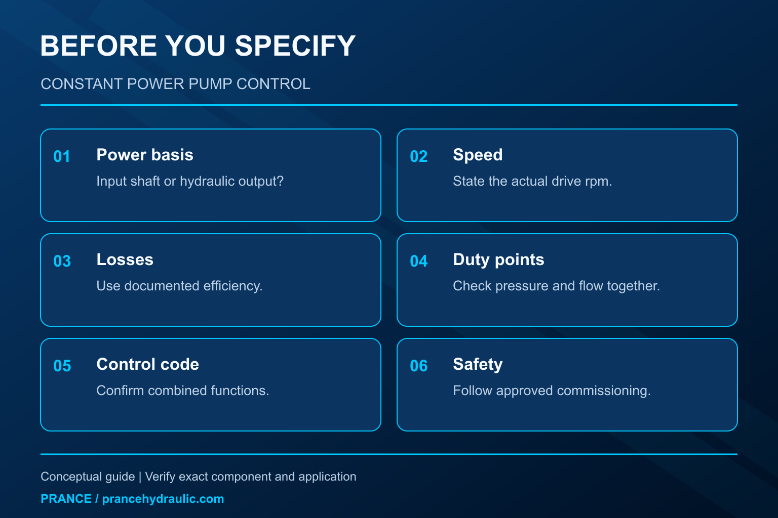
The distinction between input and output matters. Hydraulic output power is pressure difference multiplied by delivered flow. Shaft input power includes the losses inside the pump. A hydraulic output of 20 kW therefore does not establish that a 20 kW prime mover is adequate. Equally, a catalog power setting may refer to absorbed input power rather than delivered hydraulic power. Ask which quantity the published envelope represents before using it in a motor-sizing calculation.
A pump cannot force a load to consume its entire power allowance. If a valve requests little flow at low pressure, actual power can remain well below the limit. Constant power describes the limiting region available when the circuit demands it; it is not a requirement to waste the unused budget.
Read the envelope in three regions
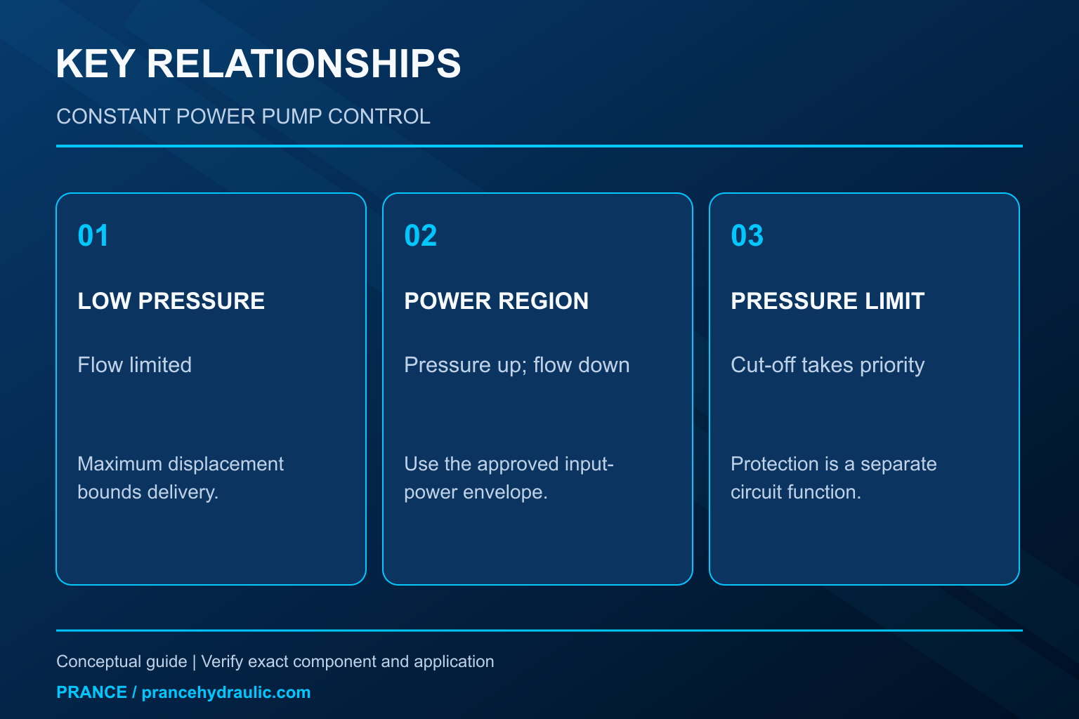
Start at low pressure. The pump may already be at its maximum permitted displacement. Flow is then bounded by displacement, speed, and volumetric losses. The power controller does not create extra displacement to maintain the same power at very low pressure. This produces a flow-limited region before the power boundary becomes active.
In the intermediate region, increasing pressure requires less flow if the same power allowance is to be respected. An ideal constant-power line is curved because flow is inversely proportional to pressure. Do not interpret an illustrative smooth curve as a measured result for a particular pump. A real controller can show tolerances, hysteresis, a segmented approximation, and different characteristics with changing temperature.
Near the pressure limit, a separate pressure controller can take priority and destroke the pump further. This upper-pressure region is not evidence that the power controller has failed. Identify the point where pressure cut-off takes over, together with the protection provided by the circuit relief system. The ordering and margins must come from the approved pump and machine documentation.
Calculate hydraulic demand with consistent units
For steady liquid flow, hydraulic output power can be estimated as P = Δp × Q / 600, where P is in kW, pressure difference is in bar, and flow is in L/min. Use the difference across the pump, not an unrelated gauge pressure elsewhere in the machine. The relationship follows unit conversion from pressure times volumetric flow; it is not a controller calibration rule.
Suppose a hypothetical duty requires 100 L/min at 120 bar. Hydraulic output is 20 kW. If the load later requires 200 bar, the same 20 kW hydraulic allowance permits only 60 L/min in the ideal calculation. An actuator whose speed depends directly on that flow will slow. That slowdown can be expected behavior even though the pump pressure remains normal.
For a planning assumption of 85% overall pump efficiency, 20 kW hydraulic output requires approximately 23.5 kW at the shaft. This efficiency is an invented example input, not a recommended universal value. Replace it with documented efficiency at the actual speed, displacement, pressure, fluid, and temperature. Add the machine’s other shaft loads separately; do not hide them inside the pump efficiency figure.
Separate power, pressure, and load-sensing functions
The table is a qualitative selection aid based on general pump-control principles. It contains no product settings or interchangeable control codes.
| Control function | Variable it responds to | Expected effect | Was es nicht begründet |
|---|---|---|---|
| Power or torque limitation | Drive loading within a defined operating range | Reduces displacement as pressure demand increases | Constant actuator speed under every load |
| Druckabschaltung | Pump outlet pressure relative to its control setting | Reduces displacement near the pressure boundary | Adequate drive power at lower pressure and high flow |
| Load sensing | Pump pressure relative to a remote load signal | Adjusts delivery to metering demand | Unlimited simultaneous-function capacity |
| Maximum displacement stop | Permitted pump geometry | Caps delivery at a specified speed | A complete power or pressure protection strategy |
A combined controller can contain several of these functions. Its behavior depends on which limitation is active at the moment. If a machine needs more flow than the available power permits, increasing a load-sensing command cannot remove the power restriction. If pressure cut-off is already active, a higher flow request also cannot make the pump exceed its permitted pressure envelope.
Why shaft speed changes the conclusion
Mechanical power equals shaft torque multiplied by angular speed. A controller that holds approximately constant input torque produces approximately constant input power only while speed remains constant. If an engine slows, the available power at that torque falls. Calling the control constant horsepower without stating speed can conceal this limitation.
For a variable-speed application, compare several operating speeds rather than scaling a single curve casually. The engine may have a different torque allowance at each speed, and auxiliary demands can change during the same work cycle. A fan, another pump section, or a driven accessory can leave less power for the main hydraulic function. A setting that is acceptable during a warm single-function test may overload the drive during simultaneous operation.
Ask for the drive torque curve, the minimum intended operating speed, and the complete shaft-load allocation. Where the machine uses electronic load management, establish how the pump’s mechanical or electrohydraulic limit interacts with that controller. A static bench curve alone does not prove protection during a rapid acceleration or a sudden load change.
Decide whether reduced flow is acceptable
Review the work cycle rather than only its highest pressure. A rapid approach phase may require high flow at modest pressure, while a pressing or clamping phase needs high pressure with little movement. Those phases can fit a power-limited pump well because their extreme flow and pressure requirements do not occur together.
A different machine may require high flow and high pressure simultaneously for a sustained cutting or traction condition. Reducing delivery could miss the required cycle time or vehicle performance. List those combined duty points explicitly. If a point sits outside the permitted envelope, the solution may involve a larger drive, a revised duty cycle, or another circuit architecture. Changing the controller label is not a substitute for the missing power.
Also distinguish average demand from peak demand. A motor’s short-term capability and the pump’s intermittent limits have their own conditions. Do not use a brief peak allowance to justify continuous operation. An energy-storage arrangement, if present, requires its own capacity, control, and safety analysis.
Diagnose an unexpected reduction in flow
First establish that the observed flow is actually below the documented envelope at the measured speed and temperature. Record pump pressure, delivered flow, shaft speed, and the command or load-sensing condition at the same time. Readings taken during different parts of the cycle can create a false pressure–flow pair.
If flow falls as pressure rises and the corresponding drive loading remains near the approved limit, the power control may be doing its job. If flow falls early with low drive loading, investigate which other control is active, whether the command reaches the controller, and whether inlet supply or internal leakage is limiting delivery. A power calculation narrows the investigation; it does not identify a worn component by itself.
Avoid raising a power setting to cure engine lugging, overheating, or a slow actuator without finding the cause. That change can increase drive overload or coupling stress. Any controlled test must follow the machine manufacturer’s procedure, with guarded moving parts, secured loads, appropriate instrumentation, and defined stopping conditions. Isolate and release stored energy before opening connections or changing hardware.
Specify a replacement without assuming control equivalence
Prance’s A10VO 31-series product page provides a starting point for discussing a variable-displacement pump. The family name and exterior photograph do not confirm a constant-power option or its calibration. Submit the complete existing code, the approved curve, rotation, mounting, shaft, port layout, fluid, speed range, and required control behavior for a configuration review.
State the power allowance at a named shaft speed and identify whether it is shaft input or hydraulic output. Include maximum flow, pressure cut-off, duty duration, and any remote command requirements. If the existing unit has a special control combination, retain its schematic and setting record. A physically fitting pump with a different control priority can change the machine’s response significantly.
Acceptance should cover several duty points on both sides of the power-control transition. Compare delivered flow, drive loading, pressure limiting, and response during a representative cycle. Document the agreed tolerances before ordering so that a normal reduction in flow at higher pressure is not later mistaken for a defective replacement.
Häufig gestellte Fragen
Ist eine Konstantleistungsregelung dasselbe wie ein Druckkompensator?
Nein. Die Leistungsbegrenzung schränkt die vom Antrieb verfügbare Druck-Volumenstrom-Kombination ein. Ein Druckkompensator reagiert auf eine Druckgrenze. Eine Pumpe kann beide Funktionen kombinieren, wobei sich die jeweils aktive Begrenzung während des Zyklus ändern kann.
Does a constant-power pump always draw its rated power?
No. Actual consumption depends on the circuit demand and losses. The power setting limits an operating envelope; a lightly loaded circuit does not have to use the entire allowance.
Why does cylinder speed decrease when pressure rises?
If power limitation is active, the pump reduces displacement and flow as pressure increases. With unchanged cylinder geometry, less supplied flow means lower movement speed. Confirm the measured point against the approved envelope before diagnosing a fault.
Can the hydraulic output calculation size the electric motor directly?
It is only the first step. Account for pump losses, other shaft loads, drive characteristics, starting conditions, and the required duty. Use documented efficiencies instead of treating an illustrative percentage as a product specification.
Can Prance confirm the control from a housing photograph?
A photograph helps identify visible interfaces but cannot prove the internal control combination or calibration. Supply the complete code and operating requirements together with the relevant drawing and curve.
Produktdaten und entsprechende technische Ressourcen
The Variable Displacement Pump OEM A10VO 31 Series provides a relevant product family for a configuration inquiry. The family name and source exterior photograph do not establish the availability of every control or option discussed here. These conceptual illustrations do not depict product internals or establish operating limits. Confirm the complete code and approved documentation. Related resources: Verstellpumpe OEM A10VO Serie 31, Hydraulikpumpen-Sortiment, Load-Sensing-Pumpe vs. druckkompensierte Pumpe: Regelungsumterschiede, Variable Vane Pump Pressure Compensation: Cam-Ring Control Explained.
Sources and limits of this guide
University and government references support general engineering and safety principles. This guide supplies independent selection reasoning and explicitly hypothetical calculations. No reference-manufacturer control codes, settings or ratings are specifications for a Prance product. Confirm the complete ordered configuration.
- NPTEL: Grundlagen der industriellen Ölhydraulik und Pneumatik
- NIOSH: preventing injury from uncontrolled hazardous energy
- VSB Technical University of Ostrava: hydraulic mechanisms, pump and motor control
University lesson: operating principles
NPTEL-NOC IITM presents 3.2 – Hydraulic Pumps. The lesson supports the pump flow, power and circuit fundamentals used in this discussion; it is not a model-specific performance or installation approval.