Wenzhou Prance Hydraulic Equipment Co., Ltd.

Hydraulic Motor Noise: Air Entrapment, Mechanical Contact, and Commutation
Hydraulic motor noise associated with air entrapment needs a structured diagnosis: record when the sound occurs, compare motor operation with reservoir and supply conditions, and separate fluid-related symptoms from mechanical contact and normal cyclic operation. A crackle, whine, or rattle alone does not identify the cause. Entrained air, a locally starved motor port, a loose mounting, and a driven machine can produce overlapping symptoms. Stop operation when noise accompanies loss of control, leakage, overheating, or abnormal vibration. This guide explains external checks and evidence to collect before a qualified technician opens a circuit or replaces a motor.
Start with the event, not the sound label
Describe what the machine was doing when the noise began. Useful distinctions include a cold start, a direction change, steady rotation under load, deceleration, and restarting after a maintenance intervention. Record whether the sound follows motor speed, commanded flow, load, or only one direction. These observations narrow the next test without turning a subjective sound into a diagnosis.
Locate the apparent source from a safe position. A rigid frame can transmit vibration from a pump, valve, gearbox, or driven shaft to the motor mounting. The loudest panel may be a resonating surface rather than the originating component. Keep guards installed and avoid putting a hand, tool, or listening probe against rotating equipment. Where acoustic or vibration measurements are needed, arrange suitable equipment and a safe measurement procedure.
A change from the machine’s established behavior matters more than comparing it with an unrelated motor. A low-speed orbital motor and a high-speed piston motor need not sound alike. Product family, installation stiffness, speed, pressure, and fluid temperature all affect the observation. Record the full motor identification and circuit revision before interpreting a change.
Distinguish entrained air from insufficient filling
Entrained air consists of gas carried as bubbles in the hydraulic fluid. It may enter upstream through a suction-side leak, return-flow agitation, inappropriate reservoir conditions, or a maintenance operation that left air in the system. Visible reservoir foam can support an investigation, but neither foam nor a milky-looking sample proves what is occurring inside a motor. Water contamination and other conditions also require consideration.
Cavitation describes local vapor formation when absolute pressure becomes sufficiently low for the fluid and temperature involved. An overrunning load can create inadequate filling at a motor port if the circuit cannot provide the required flow. That situation differs from air already mixed into the oil. Both may cause noise, and both can occur in a system, so a useful report keeps the two explanations separate.
Do not infer motor inlet conditions from pump outlet pressure alone. Valves, restrictions, acceleration, directional changes, and load behavior affect local pressure. A gauge at a distant manifold may miss the event. Pressure measurement, including its location, range, response, and reference, belongs in a qualified diagnostic plan. This article does not prescribe a universal minimum port pressure or a generic make-up valve setting.
For the pump-side distinction, consult the separate aeration and cavitation guide. For an overrunning motor circuit, the motor anti-cavitation valve discussion explains why make-up flow is a circuit-design question. Neither topic substitutes for checking the actual motor and machine documentation.
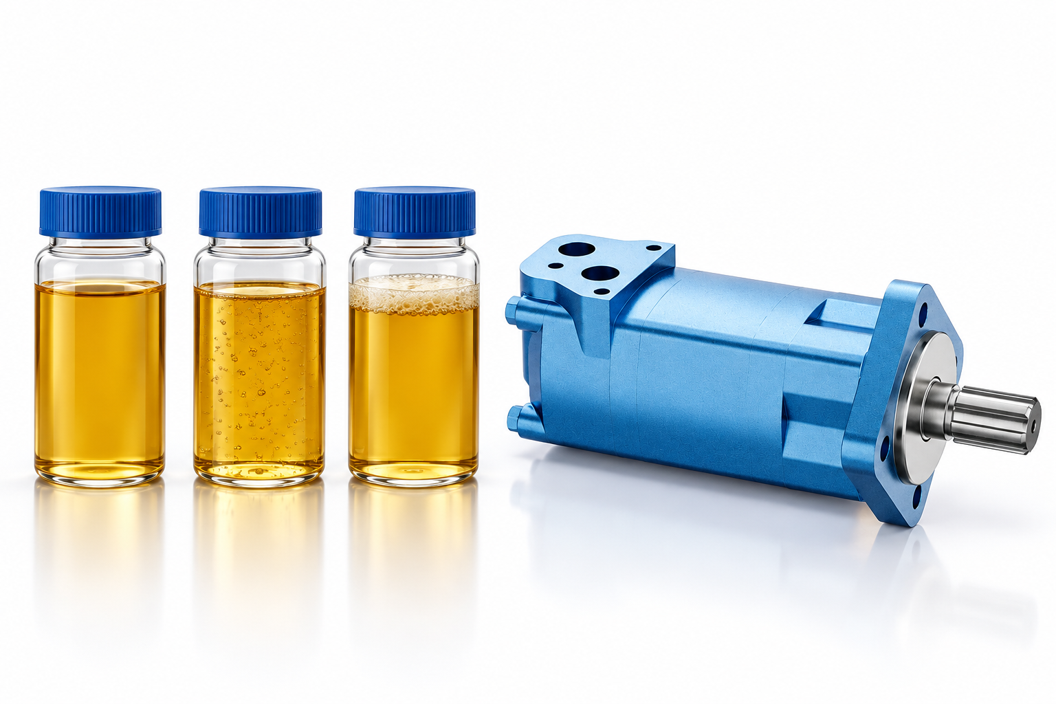
Use an observation table to choose the next check
The following table organizes qualitative observations. It supplies no pass/fail limits and does not authorize operation with a suspected fault. More than one row can apply to the same machine.
| Beobachtung | Possible explanation to investigate | Useful next evidence | Interpretation limit |
|---|---|---|---|
| Noise begins after hose replacement or servicing | Air introduced during maintenance or an incorrect connection | Service record, approved filling procedure, port identification | Timing alone does not prove trapped air |
| Reservoir shows persistent foam while motor sounds irregular | Air entry, return agitation, fluid or reservoir issue | Oil condition, reservoir level and return arrangement records | A visible sample does not identify the source |
| Noise occurs mainly during deceleration or with an overrunning load | Inadequate local filling or load-control interaction | Circuit schematic and appropriately captured motor-port pressures | Do not add or adjust a valve from sound alone |
| Clicking follows shaft rotation and changes with mechanical load | Coupling, mounting, gearbox, or driven-machine contact | Guarded external inspection and maintenance history | Stop if contact or abnormal vibration is suspected |
| Regular sound repeats at a stable operating point | Cyclic displacement or distribution behavior, or periodic mechanical excitation | Baseline recording and trend at matched conditions | A regular rhythm does not prove that the motor is healthy |
| Noise increases with temperature and declining output | Leakage, viscosity, thermal, or mechanical deterioration | Approved temperature, pressure, flow, speed and drain checks | Temperature alone cannot identify wear |
Check external conditions before changing settings
Begin with observations that do not require opening the hydraulic circuit. Verify that the reservoir level was checked in the machine’s specified condition; actuator positions and oil temperature can affect the apparent level. Look for a maintenance event, a changed fluid, an altered hose route, or a replaced filter immediately preceding the noise. Compare findings with the approved service record rather than relying on memory.
Inspect accessible hose routing, clamps, mounting fasteners, and guards only under the machine’s safe procedure. A hose touching a panel may radiate sound even if the motor is functioning normally. A loose support or changed pipe restraint can create a new resonant path. Correcting a mechanical contact requires isolation and an appropriate repair, not an improvised clamp or a hand placed on the hose while running.
Review fluid condition through approved sampling arrangements. Do not loosen a fitting to see whether bubbles emerge. A clear bottle collected improperly can introduce its own air and contamination, and a surface sample may not represent the circulating oil. Record sample location, sampling method, operating condition, and elapsed time before examination. Use laboratory analysis when contamination is suspected and the result will affect the repair decision.
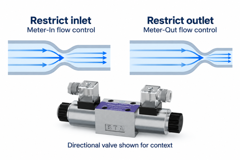
Never adjust a relief valve, counterbalance valve, or flow control merely to make the noise quieter. A quieter machine can still have an unsafe pressure or load condition. Any setting change needs a documented purpose, approved limits, suitable instruments, and a way to restore and verify the intended operating state.
Separate mechanical contact from fluid-related noise
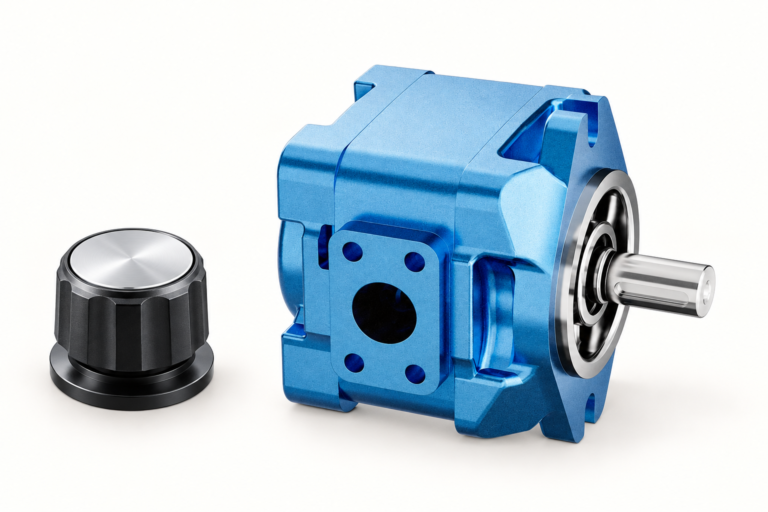
Consider the complete torque path: motor shaft, coupling, bearings, gearbox, and driven mechanism. The BMS orbital motor product entry provides the real exterior reference used in the illustrations. Its photograph cannot establish coupling alignment, allowable external load, bearing condition, or the internal construction of a particular delivered motor. Confirm the complete ordering code and supplied documents.
A damaged coupling, an alignment problem, or contact in the driven equipment may produce a repeated click or knock. The pattern may change with torque or direction, but that remains a hypothesis until inspection or measurement supports it. Do not run an uncoupled motor as an informal test: removing the load can change overspeed risk, mounting requirements, and the circuit response. Any separation test must be planned for that installation.
If vibration measurements are available, compare equivalent points at matched speed, temperature, and load. A single overall reading gives limited diagnostic information. Trends and repeatable operating conditions are more useful than claiming a universal acceptable vibration level. For an unfamiliar motor, obtain the manufacturer’s applicable guidance rather than transferring a threshold from another machine class.
Interpret cyclic sound without promising a diagnosis
Hydraulic motors produce torque through repeating working cycles. Flow distribution and displacement events can create periodic excitation. An orbital motor can therefore have a different sound character from other motor types. Normal cyclic behavior is a possible explanation, but it cannot be used to dismiss a new rattle, a loss of speed, or rising temperature.
Record shaft speed and the recording conditions if comparing sound over time. A phone recording may help a remote engineer recognize when an event happens, yet automatic gain control and background noise prevent it from serving as a calibrated acoustic measurement. State the distance, load, direction, and whether guards or panels changed. Do not use an uncalibrated recording to claim a sound-pressure rating.
If a periodic noise has always existed and performance remains stable, compare it with the established baseline and approved operating envelope. If it appeared suddenly, investigate the change. Avoid identifying an internal distribution fault from rhythm alone; confirmation may require pressure, flow, leakage, or controlled workshop inspection beyond the external checks described here.
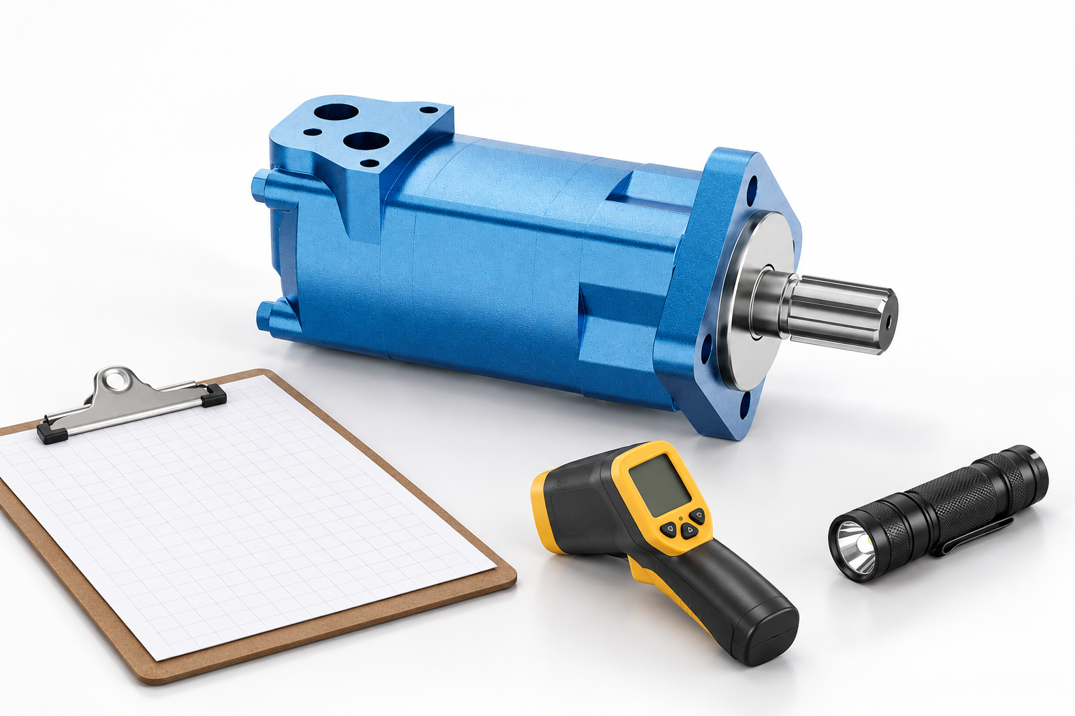
Plan measurements and stop conditions
A useful test plan states the question each instrument will answer. Motor-port pressures can help investigate filling and load interaction; supply flow and shaft speed can clarify whether commanded motion matches actual motion. Temperature trends and any applicable drain measurement can add context. Drain arrangements differ between motor codes, so do not assume that a visible port is a drain or apply a generic drain-flow rejection limit.
Pressure connections and fluid lines can retain hazardous energy after the power supply is switched off. The NIOSH hazardous-energy guidance explains why an energy-control procedure is essential. Isolate the machine, secure loads, address stored energy, and verify the safe state before intrusive work. A person loosening a line to bleed air can be exposed to injection injury and unexpected movement.
Stop the test for unexpected movement, a developing leak, abnormal vibration, rapidly increasing temperature, or a loss of control. Also stop when the planned operating limit or machine procedure requires it. Do not keep running a noisy motor to collect a more convincing recording. The next useful result may be a safe shutdown and a documented inspection request.
Send an evidence package before ordering a replacement
Include the motor nameplate or full code, machine application, circuit schematic, required speed and torque, direction of rotation, duty cycle, fluid identification, and temperature conditions. Describe the event sequence and whether the noise existed before recent maintenance. Add measured pressures and flows only with their locations, units, instrument details, and operating conditions.
State what remains unknown. For example, reservoir foam was observed but its cause was not established; or a knock followed load reversal but the coupling was not yet inspected. This lets a supplier or service engineer distinguish evidence from assumptions. A request that simply says “motor cavitation” can steer the review toward a diagnosis that has never been verified.
For replacement selection, use the Hydraulikmotor-Palette und die motor operating overview as starting points. A matching appearance or displacement alone does not establish interchangeability. Verify mounting, shaft, ports, speed, pressure, load capability, fluid requirements, and the permitted drain arrangement for the exact code.
Häufig gestellte Fragen
Does a noisy hydraulic motor always contain trapped air?
No. Mechanical contact, a driven component, periodic hydraulic excitation, inadequate local filling, or air carried in the fluid can produce overlapping sounds. Diagnose from the operating event, circuit information, measurements and inspection rather than a sound description alone.
Can I bleed air by loosening a motor hose?
Do not loosen a pressurized connection or improvise a bleeding method. Follow the machine and motor manufacturer’s approved filling and commissioning procedure, with isolation and stored-energy control. The correct method depends on the circuit and component arrangement.
Does foam in the tank prove motor cavitation?
No. Foam can justify investigating aeration, return agitation or fluid condition, while cavitation concerns local vapor formation under low absolute pressure. Tank appearance does not establish the pressure at a motor port or identify the initiating fault.
Should I adjust the relief valve to reduce the noise?
A quieter sound does not prove a safe repair. Changing a relief or load-control setting can alter pressure and machine behavior. Use a documented test plan and approved component limits; do not tune the circuit by ear.
What information helps a supplier investigate the noise?
Provide the full motor code, circuit schematic, speed and torque duty, fluid and temperature, event timing, maintenance history, and safely collected recordings or measurements. Identify instrument locations and separate observed facts from suspected causes.
Produktdaten und entsprechende technische Ressourcen
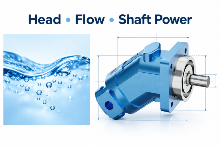
The Hydraulic Gerotor Orbit Motor BMS catalog exterior is used as the real product reference in these explanatory images. It does not establish the approved service method, optional construction, or operating limits for an individual order. Confirm the complete code and its documentation. Related resources: Hydraulischer Gerotor-Orbitmotor BMS, Hydraulikmotor-Palette, Was ist ein Hydraulikmotor?, Radialkolbenmotor – Funktionsprinzip: Drehmoment bei niedriger Drehzahl.
Sources and limits of this guide
NPTEL supports hydraulic motor operating principles; the FAA handbook discusses hydraulic fluid and air-related system concerns in aircraft, without providing industrial motor settings; NIOSH supports hazardous-energy isolation. This is a qualitative diagnostic guide, not a model-specific service procedure.
- NPTEL: Grundlagen der industriellen Ölhydraulik und Pneumatik
- FAA: Aviation Maintenance Technician Handbook, Airframe Volume 2, hydraulic-system principles
- NIOSH: Verletzungen durch gefährliche Energie verhindern
University lesson: operating principles
NPTEL-NOC IITM presents 6.3 – Hydraulic Motors. The lesson supports the motor operating principles when separating periodic hydraulic excitation from a fault diagnosis used in this discussion; it is not a model-specific performance or installation approval.