Wenzhou Prance Hydraulic Equipment Co., Ltd.

Hydraulic Motor Anti-Cavitation Valve: When Make-Up Flow Is Needed
A hydraulic motor anti-cavitation valve provides an approved make-up flow path when a working line needs oil, particularly during load-driven motion or rapid changes of operating state. It does not replace overpressure protection, load control or a suitable supply circuit. Select the valve from the required flow, available source pressure, connection arrangement and motor filling conditions rather than from thread size alone.
This guide explains how replenishment works and what engineers and buyers should verify. It avoids a universal valve setting because the correct arrangement depends on the motor, circuit and machine duty.
Identify when the motor can demand make-up oil
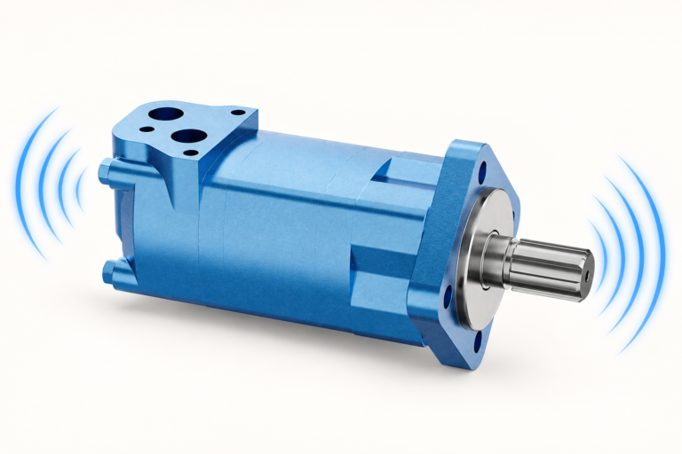
A rotating load can continue driving the shaft after supply flow decreases or a directional valve changes position. The motor can then act as a pump, expelling oil from one side and requiring oil on the other. If the receiving side cannot fill adequately, pressure can fall and harmful low-pressure conditions can develop.
Starting, deceleration, reversal and load overrunning can create different demand patterns. Record the actual operating event rather than assuming cavitation occurs only at high speed. A circuit that runs steadily without noise may still have a problem during a short transition. Review speed, pressure and command on the same timeline.
Distinguish anti-cavitation from crossover relief
A crossover relief arrangement limits pressure by providing an approved path from a high-pressure working line. An anti-cavitation or make-up check path supplies oil to a line requiring replenishment. The functions may appear together in a motor valve block, but they address different conditions and have different selection requirements.
Do not describe a relief valve as sufficient low-pressure protection without verifying the circuit paths. Oil discharged from the high-pressure side may not always provide the amount or destination required for filling. Likewise, a make-up valve does not limit high pressure by itself. Identify each element in the schematic and state its specific role.
Determine the replenishment source
Make-up oil can come from an approved tank, return, charge or other circuit path. Establish the available pressure and flow at the valve under the demanding conditions. Tank head, return pressure, charge pressure and line losses can affect what reaches the motor. Use consistent pressure references when evaluating the margin.
A source that looks adequate during one machine function may become restricted or unavailable during another. Check simultaneous operation and the failure state. Do not assume a return manifold always supplies clean, sufficiently pressurized oil. The source must be compatible with the motor and the machine's contamination and temperature requirements.
Read the check-valve opening and flow characteristics
A check valve opens according to pressure difference and its design, but cracking pressure alone does not describe full-flow performance. Review the pressure-drop curve at the required make-up flow. A valve can begin to open and still create excessive restriction at the relevant speed or transient demand.
Confirm connection direction and any pilot or integrated features. A cartridge installed in the wrong cavity or an incorrectly connected block can prevent the intended flow. Verify the assembly drawing and part numbers rather than identifying the function from a similar-looking housing. Include adapters and internal passages in the total restriction review.
Estimate demand with the motor duty
Theoretical displaced flow relates to displacement and shaft speed, but actual make-up demand depends on the operating state and other available paths. Use a documented circuit calculation or supplier analysis rather than assuming that all inlet flow must come through the make-up valve at all times.
For a preliminary illustration, a 100 cubic-centimeter-per-revolution unit turning at 300 rpm displaces about 30 L/min theoretically. This does not specify a make-up valve for any product. Leakage, changing speed, fluid condition and circuit paths must be considered, and the motor's permitted low-pressure condition remains configuration-specific.
Include cold oil and rapid transitions
Oil viscosity affects pressure loss through lines and valves. A warm steady-flow test may not represent a cold deceleration event. Check the actual fluid temperature range and use appropriate pressure-drop data. Small fittings or long lines can consume the available replenishment margin before oil reaches the motor.
A rapid event also requires consideration of response and local fluid volume. Average flow measured over a long interval can hide a short demand. Use instruments suitable for the transition and record the setup. Do not conclude that make-up protection is adequate from a slowly varying supply gauge alone.
Compare selection requirements in a table
| Auswahlobjekt | Was zu überprüfen ist | Consequence of an incomplete check |
|---|---|---|
| Source path | Available oil, pressure, temperature and cleanliness | Valve may open without adequate filling flow |
| Valve flow capacity | Pressure drop at the required flow | Cracking pressure may hide full-flow restriction |
| Circuit direction | Correct check orientation in both shaft directions | One operating state may remain unprotected |
| Connection passages | Block, fittings, hoses and adapters | Local restriction can dominate the complete path |
| Dynamic event | Deceleration, reversal and overrunning demand | A steady test may miss transition problems |
| Related protection | Relief, braking and load-control paths | Make-up alone cannot control all machine behavior |
The table defines a complete selection review. It does not substitute for the selected motor's filling and pressure requirements.
Place the valve according to the approved circuit
Motor-mounted protection can reduce the distance between the valve and working ports, but location alone does not prove adequate performance. Internal passages, source routing and the complete block design still matter. A remote valve requires evaluation of the connecting lines and their effect on the operating event.
Use the circuit designer's approved location and arrangement. Do not add a check valve near the motor without confirming its source and its effect on other functions. An added path can change stopping, isolation or load-control behavior. The benefit must be verified as part of the machine rather than inferred from the component name.
Diagnose symptoms without assuming cavitation
Noise, rough movement or damage can result from low-pressure filling problems, but they also have other causes. Compare pressure at both work ports, shaft speed, valve command and temperature. Determine whether the load was driving the motor and whether the make-up path was available at that moment.
Inspect source restrictions and valve condition using the service instructions. Debris, incorrect assembly or a mismatched cartridge can affect operation. Preserve the original settings and connections before making changes. Repeatedly increasing supply pressure without identifying the low-pressure event may not address the underlying issue.
Keep the case drain and flushing functions separate
Case drainage removes housing leakage and any specified cooling flow. A flushing valve exchanges oil in an approved circuit path. Neither should be treated as an improvised make-up connection. Their pressure and flow requirements differ from working-line replenishment.
If a valve block integrates several functions, identify each path and its destination. Ask whether published drain flow includes flushing and whether the charge circuit must supply additional cooling flow. A change made to improve replenishment can affect the charge-flow budget, so review the complete arrangement rather than adjusting one valve in isolation.
Validate through the actual operating events
After assembly, confirm part numbers, check direction, source continuity and correct connections. Use the approved commissioning procedure with the load controlled. Record relevant working pressures, speed, command and source condition during starting, deceleration and reversal. Include the demanding cold or simultaneous-duty condition where practical.
Compare observations with the selected motor and circuit acceptance requirements. If a low-pressure excursion remains, determine whether the source, valve capacity, routing or sequence is inadequate. A valve that opens on a bench is not proof that the installed circuit fills the motor during the real event.
Specify the valve in the RFQ
Provide the motor code, displacement range, speeds, circuit schematic and events requiring replenishment. State the make-up source, available pressure and flow, fluid and temperature range. Include whether the motor can overrun and which elements control braking and pressure.
Request the exact valve or block configuration, opening characteristics, full-flow pressure-drop data and connection drawing. Ask for confirmation at the specified duty and identify any required source or plumbing changes. A quotation containing only a cartridge size and cracking pressure leaves important system questions unanswered.
Record replacement cartridge markings and the block drawing revision after service. This allows the next technician to verify the installed flow path without guessing from the external housing.
Häufig gestellte Fragen
Is an anti-cavitation valve the same as a relief valve?
No. A make-up path supplies oil to a line needing replenishment, while a relief path limits excessive pressure. A circuit may need both functions with a defined arrangement.
Is low cracking pressure enough for selection?
No. Check pressure drop at the required flow, the available source pressure and the complete line and block losses. Initial opening is not full-flow acceptance.
Can a valve prevent every form of motor noise?
No. Bearings, pulsation, alignment and other conditions can create noise. Verify the relevant pressure and flow event before diagnosing cavitation.
Does a tank connection always provide enough make-up oil?
Not automatically. Source pressure, elevation, restrictions, fluid condition and operating state determine what reaches the valve and motor.
What is the best installed test?
Reproduce the approved demanding events while recording both work pressures, speed, command and source condition. A steady unloaded test alone is insufficient for a transition-related problem.
Produktdaten und entsprechende technische Ressourcen
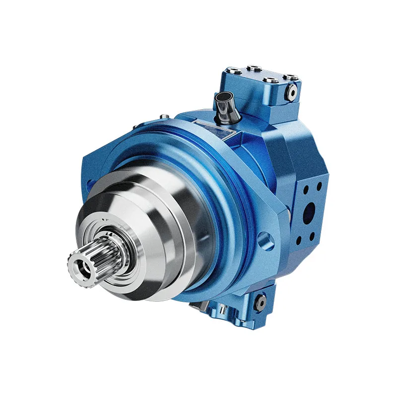
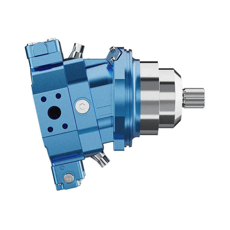
Für eine Anfrage zu einem bestimmten Produkt, bitte überprüfen Sie Hydraulischer Schrägachsen-Konstantkolbenmotor A6VE und die vollständige Spezifikation und Installationsbedingungen zu liefern. Bereich der Kolbenmotoren, Bereich der Orbitalmotoren, Motorkasten-Druckkontrollen, Motorabfluss-Durchflussmessung, Berechnung der Motorleistung, Hydraulic Motor Freewheeling Circuit: Bypass and Make-Up Flow, Hydraulic Motor Flushing Valve: Closed-Loop Cooling Explained. Die Produktfotos veranschaulichen die Katalogkonfigurationen; sie geben jedoch keine Druck-, Geschwindigkeits- oder Wellenlastwerte für eine nicht bestätigte Bestellung an.
Lehrveranstaltung an der Universität: Grundlagen des hydraulischen Motors
NPTEL-NOC IITM stellt eine Lehre über den hydraulischen Motor aus dem Institut für Technik und Ingenieurwissenschaften in Madras vor. Die Vorlesung unterstützt die Unterscheidung zwischen hydraulischem Eingangs- und Abtrieb, wie in dieser Anleitung beschrieben. Die spezifischen Installationseinstellungen und Betriebsgrenzen des jeweiligen Bauteils erfordern weiterhin die Dokumentation des ausgewählten Motors.
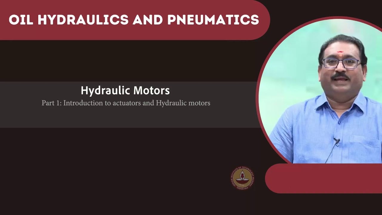
Öffnen Sie die NPTEL-Vorlesung zu Hydraulikmotoren.
Technische und Sicherheitsreferenzen
- NPTEL: Grundlagen der industriellen Ölhydraulik und Pneumatik
- NIOSH: Verletzungen durch gefährliche Energie verhindern
- Technische Referenz: Prinzipien des Betriebes von Orbitalmotoren und Installation
Diese Referenzen liefern ein pädagogisches und technisches Kontext. Die spezifischen Bewertungen für bestimmte Modelle von Referenzherstellern sind keine Spezifikationen für ein Prance-Produkt und implizieren keine Zugehörigkeit oder Genehmigung der jeweiligen Marke.