Wenzhou Prance Hydraulic Equipment Co., Ltd.

Closed-Circuit Pump Pressure Limiter vs High-Pressure Relief
A closed-circuit pump pressure limiter and a high-pressure relief valve can both restrict loop pressure, but they act differently. A pressure limiter changes the pump’s displacement through its control system. A high-pressure relief valve passes oil through a pressure-drop path when its opening condition is reached, generating heat. They may work together, and their settings must be coordinated using the exact pump documentation. A pressure reading near the protective setting does not identify which device is acting. Check the ordered protection package, both loop pressures, displacement response and temperature before deciding that a valve requires adjustment.
Start with the closed-loop pressure difference
A hydrostatic closed loop has two working lines whose high- and low-pressure roles can change with operating direction and load. A protection setting may be defined as differential pressure between those lines, not pressure relative to atmosphere. Record the reference used by the manufacturer’s setting procedure. Comparing a high-side gauge reading with a differential setting without measuring the low side can produce the wrong conclusion.
For an illustrative calculation only, suppose the working lines measure 260 bar and 20 bar at the relevant locations. Their difference is 240 bar. The 260-bar reading alone is not the differential pressure. These assumed values are not an AA4VG rating or a recommended setting. Verify the permitted measurement locations, instrument ranges and conditions before applying the same subtraction to a real machine.
How a pressure limiter reduces pump delivery
In the Danfoss H1T reference architecture, a pressure limiter changes servo pressure when the loop reaches its setting. That moves the swash plate to reduce displacement under a resisting load. Less displacement means less delivered flow at the same shaft speed, so the pump can control pressure without continuously passing the main delivery across a high-pressure relief. This describes the referenced design; it does not establish every available AA4VG control option.
At a stalled resisting load, the pump can move toward neutral while maintaining the pressure needed by the circuit. Near neutral does not mean that every flow, leakage and mechanical loss disappears. Nor does pressure limiting prove that the machine is safe to hold a suspended load. The motor, brake, load controls and mechanical restraints must perform their own specified functions independently of the pump’s pressure-control description.
How high-pressure relief limits the loop
The same reference describes dedicated high-pressure relief and charge-check functions for the loop sides. Excessive pressure opens a flow path from the high-pressure side toward the low-pressure side through the specified arrangement. The precise internal route depends on design. It should be taken from the schematic rather than described as a universal direct connection between two external ports.
The relief process dissipates hydraulic power. Repeated or sustained operation can heat the loop and damage components. A relief opening is therefore not an efficient speed-control strategy for a continuously stalled drive. The valve remains an important protective element, but the permissible duty and the relationship to other controls must come from the selected pump’s documentation and the machine design.
Compare the behaviors under the same load
This qualitative comparison follows the referenced H1T service description. It is a functional guide, not a statement that every Prance closed-loop pump has both devices.
| Frage | Pressure limiter | High-pressure relief |
|---|---|---|
| Main action | Changes pump displacement through control action | Opens a pressure-dependent flow path |
| Response to a resisting stall | Can reduce delivery toward that needed to maintain pressure | Can pass flow while the pressure drop dissipates power |
| Main diagnostic evidence | Pressure together with command and displacement response | Pressure together with relief-flow or thermal evidence |
| Setting interpretation | May be loop differential pressure | Must follow its specified reference and test flow |
| Configuration question | Is the option installed on both required loop sides? | What relief cartridges, directions and factory settings apply? |
| Unsafe assumption | Neutral-like displacement means a secured load | Relief operation is harmless for unlimited time |
A useful comparison keeps shaft speed, command, temperature and load direction consistent. A cold test at one command and a warm test at another cannot isolate the behavior of a particular protective function. Avoid repeated stall testing merely to gather matching data; use the approved diagnostic procedure and its time limits.
Why setting coordination matters
In the H1 reference design, where pressure limiting and high-pressure relief are combined, the relief setting is above the limiter setting. This allows the displacement control to act during its intended operating range while the relief provides the specified protection above it. The manufacturer’s exact setting method and separation remain specific to that design and operating condition. Do not transfer an offset from a different series.
Relief pressure can also depend on the flow passing through the valve. A value measured at one test flow need not describe the pressure during a much larger relief event. An order-code value, a factory test condition and a field peak are different pieces of evidence. Ask what each number means before deciding that a field measurement proves a bad cartridge or an incorrect factory setting.
Heat calculations help explain the consequence
For an idealized pressure-drop path, dissipated hydraulic power in kilowatts is approximately pressure difference in bar multiplied by flow in liters per minute, divided by 600. If an assumed 8 liters per minute crosses an assumed 240-bar drop, the hydraulic power dissipated is 3.2 kilowatts. This is an illustrative energy calculation, not an estimate of actual relief flow in a particular pump and not a Prance performance claim.
The calculation explains why a relatively small sustained relief flow can matter thermally. It does not identify the heat source by itself: leakage, charge relief, bearings and other restrictions also contribute. Do not assume that the entire pump delivery crosses the relief, or infer relief flow from temperature alone. A measured heat problem requires a circuit-specific energy balance and the permitted diagnostic evidence.
Distinguish protection action from an unrelated fault
A drive that stops accelerating while pressure stabilizes may be reaching an intended pressure limit, or it may have a different problem. Insufficient control supply, restricted command, a mechanical load or excessive leakage can all affect output. Check whether the displacement command and servo response follow the specified behavior before assigning the symptom to pressure limiting. A pressure plateau is a clue, not a complete diagnosis.
Unexpected heating also needs context. Determine whether it occurs at neutral, during acceleration, while holding a resisting load or during overrun. Those conditions can involve different flow paths. Compare both directions where the approved procedure permits, because the pump may have separate protection elements or settings for each side. A directional difference should be reconciled with the order code before it is called a fault.

cURL Too many subrequests by single Worker invocation. To configure this limit, refer to https://developers.cloudflare.com/workers/wrangler/configuration/#limits
cURL Too many subrequests by single Worker invocation. To configure this limit, refer to https://developers.cloudflare.com/workers/wrangler/configuration/#limits.
cURL Too many subrequests by single Worker invocation. To configure this limit, refer to https://developers.cloudflare.com/workers/wrangler/configuration/#limits.

cURL Too many subrequests by single Worker invocation. To configure this limit, refer to https://developers.cloudflare.com/workers/wrangler/configuration/#limits
cURL Too many subrequests by single Worker invocation. To configure this limit, refer to https://developers.cloudflare.com/workers/wrangler/configuration/#limits.
cURL Too many subrequests by single Worker invocation. To configure this limit, refer to https://developers.cloudflare.com/workers/wrangler/configuration/#limits.
cURL Too many subrequests by single Worker invocation. To configure this limit, refer to https://developers.cloudflare.com/workers/wrangler/configuration/#limits
cURL Too many subrequests by single Worker invocation. To configure this limit, refer to https://developers.cloudflare.com/workers/wrangler/configuration/#limits.
Before changing a setting, preserve the original condition and obtain the approved adjustment method. Some relief elements are factory set and are not intended for routine field adjustment. A higher setting can move the problem into a hose, motor or mechanical component rather than repair it. Following any authorized repair, verify operation in both required directions and check the original thermal symptom without exceeding the test duty.
Häufig gestellte Fragen
Does a pressure limiter replace high-pressure relief protection?
Not automatically. The installed protection package is design-specific. Some arrangements combine displacement control with separate relief functions. Verify the order code and schematic rather than removing or bypassing a protective element based on a general explanation.
Why can a pressure-limited pump still become warm?
Reducing displacement avoids sustained main-flow relief dissipation, but leakage, control flow and mechanical losses remain. Other circuit restrictions may also generate heat. Determine when heating occurs and follow the approved diagnostic procedure before identifying its source.
Can I use the same setting in both working directions?
Only when the selected configuration and machine requirements specify it. Reference designs can have independently specified loop-side settings. Confirm both sides in the order documentation and do not assume symmetry from a single gauge reading.
Is high-side gauge pressure equal to the limiter setting?
Not when the setting is defined as loop differential pressure. The low-side pressure contributes to the comparison. Measure the specified locations and use the manufacturer’s reference conditions, particularly when charge pressure or operating direction changes.
What should accompany a replacement pump inquiry?
Include the complete order code, schematic, control arrangement, both loop-side protection requirements, charge conditions and load duty. State any overrunning operation and heating symptoms. Request written confirmation of the actual protection package and its test conditions.
Verwandte Produkt- und Ingenieurressourcen
Geschlossene Verstell-Kolbenpumpe AA4VG, Hydraulikpumpen-Produktpalette, Druckkompensierte Pumpe Überschwinger: Warum konstanter Druck normal aussieht, Geschlossener Ladungsdruck: Was er liefert und wie man Verluste diagnostiziert. Bestätigen Sie den vollständigen Produktcode und die Anwendungsanforderungen bei der Anforderung einer Konfigurationsüberprüfung.
Technische Referenzen
- Danfoss H1T service manual: reference pressure protection and filtration architecture
- NIOSH: Preventing Deaths from Uncontrolled Hazardous Energy
Weiterführendes Lernen: Hydraulikpumpen
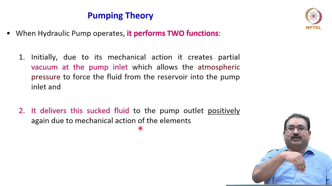
3.2 – Hydraulic Pumps by NPTEL-NOC IITM provides background on pump operating principles. Pump fundamentals explain displacement and flow; this lecture does not prescribe pressure-limiter or relief settings. It supplements the component fundamentals; it is not a test procedure for the complete circuit discussed above.