Wenzhou Prance Hydraulic Equipment Co., Ltd.

Hydraulic Pump Pressure Gauge Selection: Range, Pulsation, and Test Points
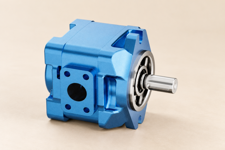
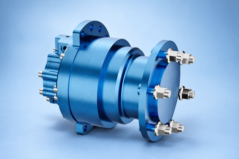
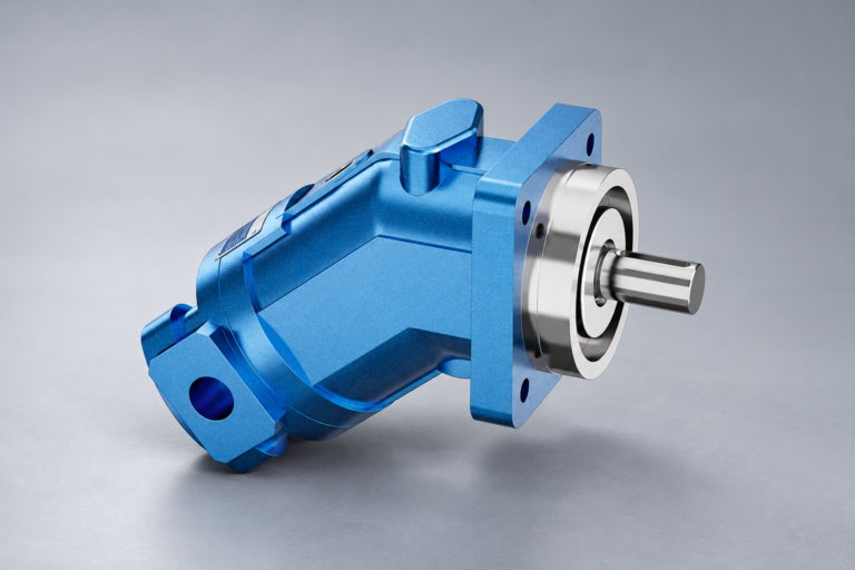
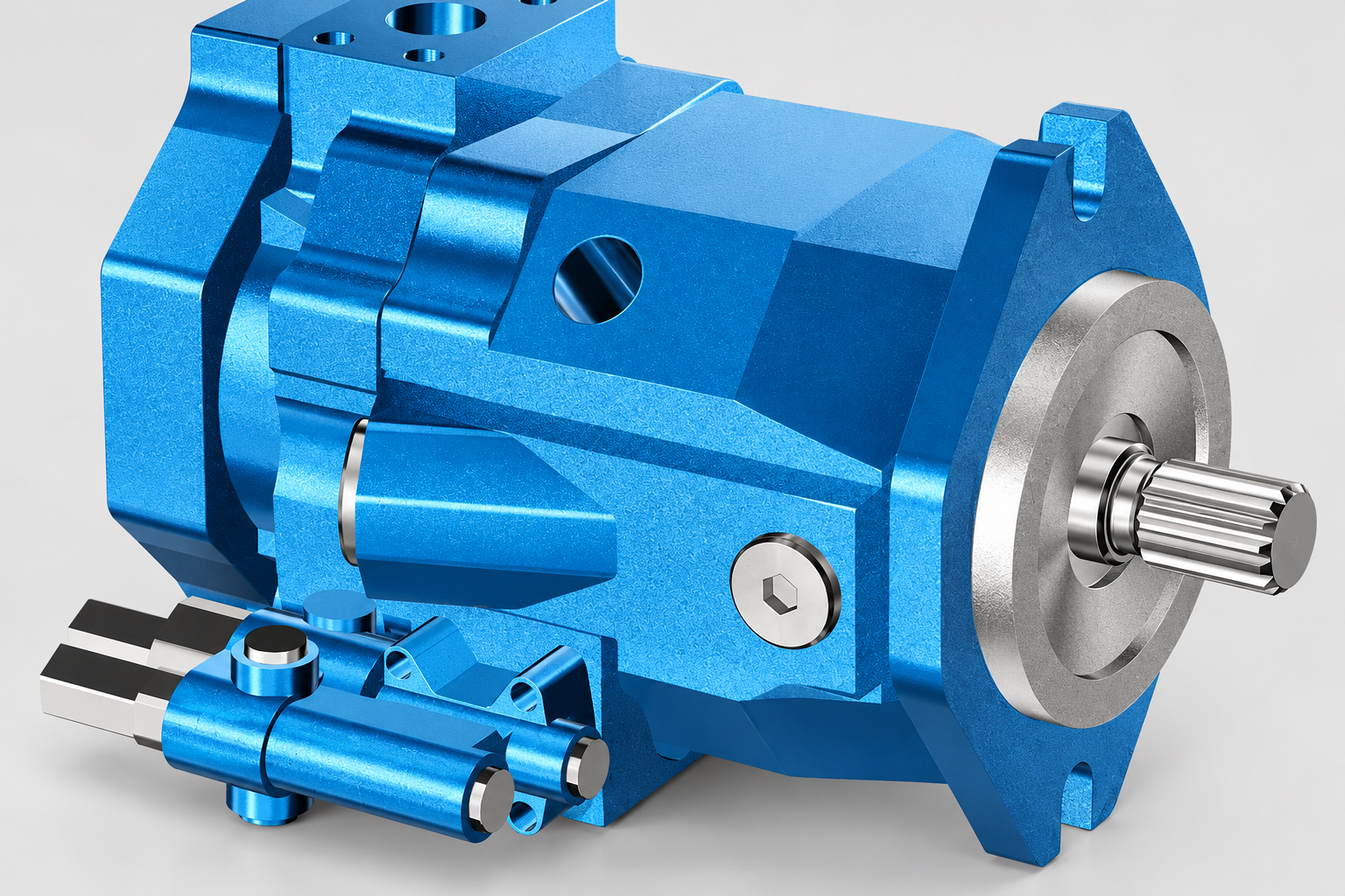
Hydraulic pump pressure gauge selection begins with the pressure you need to measure, the location of the test point and the speed of the event. The gauge must suit the operating range, possible peaks, fluid, temperature, connection and required accuracy. A damped mechanical gauge can show steady pressure well while concealing a short transient. A fast transducer can capture dynamics but requires suitable acquisition and calibration. This guide explains how to choose the measurement system and document its limits. The pump illustration is a component reference, not proof that a particular gauge or test fitting is supplied.
Define the measurement question
A gauge selected to check steady outlet pressure has a different task from a sensor recording a switching spike. State whether the objective is commissioning, pressure-control adjustment, routine observation, pressure-drop measurement or transient investigation. Define the relevant operating events and expected duration before buying an instrument.
Pressure at the pump outlet is not always pressure at the actuator. Valves, lines and fittings create differences, and dynamic events can vary by location. A gauge at one point cannot establish the pressure everywhere in the circuit. Label the test point on a drawing so the result remains meaningful after the instrument is removed.
Also define whether the quantity is gauge pressure, absolute pressure or differential pressure. These quantities use different references. An inlet condition near atmospheric pressure may require a different instrument from a high-pressure outlet. Do not reuse an outlet gauge for suction analysis without checking its range and reference.
Choose range from the whole operating envelope
The instrument range must accommodate the expected steady pressure and credible peaks while preserving useful resolution. A gauge with a very large full-scale range may survive a condition but provide poor detail at the pressure of interest. A range too close to the normal pressure can be unsuitable for fluctuating service or an unexpected event.
Follow the gauge manufacturer's permissible operating fractions, overload limits and dynamic-service instructions. There is no universal fraction of full scale that suits every instrument. Distinguish the display range from the permitted continuous load, transient overload and proof-pressure information. These terms are not interchangeable.
If the expected peaks are unknown, establish them through an engineered test plan using a suitable protected measurement system. Do not connect an inadequately rated gauge and wait to see whether it survives. Every hose, adapter, test coupling and seal in the measurement assembly must also be suitable for the pressure and fluid.
Interpret accuracy correctly
An accuracy specification may be expressed as a percentage of full scale, a percentage of reading, a fixed term or a combination. Read the complete specification. A percentage of full scale produces the same stated absolute error across the scale; its relative importance grows as the measured pressure becomes smaller.
For example, an illustrative 0–250 bar gauge with a stated error of plus or minus 1 percent of full scale corresponds to plus or minus 2.5 bar under the specified conditions. At a reading of 25 bar, that amount is 10 percent of the reading. These numbers explain the specification; they are not a recommendation or a rating for any particular instrument.
Resolution, repeatability and calibration uncertainty are separate from the manufacturer's accuracy statement. A digital display showing tenths of a bar does not independently prove accuracy to a tenth of a bar. Consider the complete measurement uncertainty when the result will determine acceptance or an adjustment close to a limit.
Mechanical gauges and transducers
A mechanical gauge provides a direct local indication and can be convenient for a steady check. Its movement, damping and installation affect how it responds to changing pressure. Read the manufacturer's instructions for vibration, mounting orientation and temperature. A liquid-filled case is not automatically a guarantee that every pressure transient is safely handled or accurately shown.
A transducer converts pressure to an electrical signal for recording or control. Select its output, supply, pressure reference, range and environmental suitability. The acquisition equipment must support the signal and required response. A fast sensor connected to a slow recorder still produces a slow measurement system.
For transient work, establish sensor response, sample rate, filtering and trigger behaviour. The necessary values depend on the event being investigated. More samples are not useful if the test connection or sensor has already damped the signal. A measurement assembly should be evaluated from the hydraulic port through to the final recorded value.
Damping, snubbers and test hoses
Damping can make a fluctuating display easier to read and protect a movement in suitable service. It also changes the information available to the observer. A damped gauge that shows a steady value cannot prove the absence of a short pressure spike. Record any snubber, restrictor or remote hose used in the setup.
A long narrow hose, trapped air or an unsuitable connection can influence dynamic response. Trapped air can introduce compliance and alter the pressure signal reaching the instrument. Install and prepare the measurement arrangement using its approved procedure. Do not assume a remote test hose faithfully reproduces all high-frequency events at the pump port.
Where both steady operation and transients matter, use a measurement plan that addresses both needs. The team may need a local indication and a separately recorded sensor. Agree how the results will be compared and which instrument answers which question. Avoid treating a convenient panel gauge as a complete diagnostic system.
Connections and wetted materials
Identify the exact thread and sealing method. Similar-looking hydraulic threads can differ in pitch, taper and sealing arrangement. A pressure gauge may use a thread that is not the same as the pump test port. Use an approved adapter and seal rather than forcing a near match or adding unspecified sealant.
Wetted materials must be compatible with the fluid and temperature. Include the fill fluid or isolation arrangement if a diaphragm seal is used. Such arrangements can add their own response and temperature effects. Confirm the assembled instrument specification rather than selecting each component independently and assuming the combination remains suitable.
A test coupling can provide a practical protected access method, but it still requires the correct mating part and pressure rating. A pump catalogue photograph does not prove that a particular coupling is present. Check the ordered drawing and installation instructions before arranging the test equipment.
A selection decision table
| Measurement need | Main selection question | Record with the result |
|---|---|---|
| Steady outlet pressure | Does range and uncertainty suit this operating point? | Range, accuracy basis and test location |
| Short switching event | Can the complete system capture the event? | Response, sample rate, filtering and trigger |
| Pump inlet condition | Is the pressure reference and low-pressure range correct? | Gauge/absolute reference and connection point |
| Pressure loss across a component | Are two measurements comparable or is a differential sensor needed? | Simultaneous readings and uncertainty |
| Routine installed monitoring | Is the instrument suitable for vibration and environment? | Mounting, damping and calibration schedule |
Supporting technical context: NIST: pressure measurement and calibration, NIST: identifying measurement uncertainty. Illustrative calculations and qualitative checks do not establish a product rating or universal acceptance limit.
This qualitative table gives selection questions rather than universal settings. Instrument documentation and calibration information establish the actual limits. Measurement uncertainty guidance supports recording the full method and conditions.
Calibrate for the range being used
A calibration record should identify the instrument, pressure reference, calibration points, uncertainty and any correction. Verify that it covers the operating range and measurement direction relevant to the test. A sticker or recent date alone does not establish the suitability of a calibration for every task.
Check zero according to the instrument instructions and note unexpected drift. Do not adjust or erase a discrepancy before recording it when it could affect past results. A comparison with another gauge can reveal disagreement, but it does not establish which is correct unless the reference and uncertainty are known.
For a consequential acceptance decision, agree the decision rule. If a measured value is close to a limit, uncertainty can affect the interpretation. Preserve the reading, correction and uncertainty rather than rounding until it appears compliant. Repeatability from several readings is useful but does not remove systematic errors.
Plan a safe pressure measurement
Install instruments with the equipment isolated and stored energy controlled. Hydraulic systems can retain pressure after the drive stops. Follow the machine's procedure for accumulators, suspended loads and trapped sections. Never loosen a gauge or fitting to check whether pressure remains.
Use suitable guarding and protected access during operation. Establish stop conditions before the test. A hose leak, abnormal vibration or an unexpected pressure trend should lead to the planned response, not an improvised attempt to tighten a fitting while pressurised. Qualified personnel must evaluate the test arrangement and circuit protection.
A gauge is a measuring device; it is not pressure protection. An instrument cannot substitute for the circuit's approved relief or other protective functions. Do not intentionally exceed component limits to discover the maximum pressure that the gauge can display.
Connect the result to pump performance
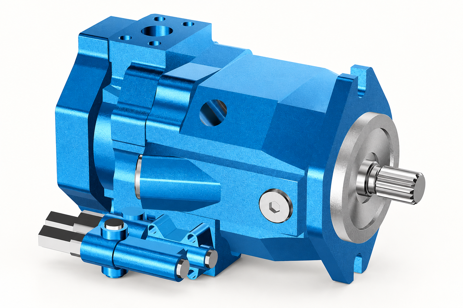
Prance's A10VSO 52 Series variable-displacement pump is a relevant family for outlet-pressure and control enquiries. The illustrations show its catalogue exterior. They do not identify a verified gauge port, demonstrate a compensator adjustment or establish a permitted pressure. Request the ordered pump drawing and control instructions before selecting a test point.
Measure pressure together with speed, flow and temperature when evaluating performance. A pressure reading alone does not establish volumetric efficiency, shaft power or a flow-control fault. The control command and operating event also matter when a pump destrokes or a machine changes load.
Retain the final record with instrument identification, test-point drawing and operating conditions. If a later reading differs, this information helps establish whether the change belongs to the pump, the circuit or the measurement method. A precise measurement record supports a much stronger purchasing or service decision than a single unqualified pressure number.
Häufig gestellte Fragen
Should I always choose a gauge with twice the working pressure?
Do not apply a universal multiplier. Follow the instrument manufacturer's continuous, dynamic and overload requirements, and consider resolution at the pressure of interest. The complete expected operating envelope governs selection.
Can a liquid-filled gauge detect a brief pressure spike?
It may damp the displayed response. A steady indication does not prove there was no transient. Use a suitable sensor and recording system when the question involves short events.
Does one percent accuracy mean one percent of the reading?
Only if the specification says so. Many instruments specify a percentage of full scale or a combined expression. Calculate the corresponding absolute error and assess its significance at the actual reading.
Can I connect any gauge thread to a hydraulic pump port?
No. Confirm thread, sealing method, adapter, materials and the full assembly's ratings. Similar appearance does not establish a safe or compatible connection.
Does a calibrated gauge prove the pump meets its specification?
It supports a pressure measurement within its documented scope. Pump performance also requires the correct test conditions and other quantities such as flow, speed and temperature. Follow an agreed acceptance method.
Related products and engineering guides
Hochdruck-Verstellpumpe A10VSO Serie 52, related hydraulic product range, Welche Aufzeichnungen sollten Druckprüfungen nach einem Bauteilwechsel unterstützen?, Hydraulikpumpen-Druckpulsation: Ursachen, Messung und Reduzierung, Hydraulic Shock Pressure: Causes, Calculation, and Protection. Provide the circuit, fluid, duty and exact ordered configuration when requesting component-specific data.
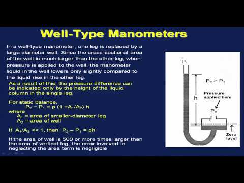
University lesson: Mod-01 Lec-42 Pressure Measurement
This NPTEL university lecture explains pressure-measurement principles and instruments from IIT Kharagpur; the general lesson supports gauge and transducer selection, while a hydraulic installation still requires its own approved pressure and connection limits.
Technical references
- NIST: pressure measurement and calibration
- NIST: identifying measurement uncertainty
- NIOSH: hazardous-energy isolation
Sources support the stated principles and method scope. Illustrative inputs and another manufacturer’s documents do not establish Prance component ratings, warranties or brand affiliation.