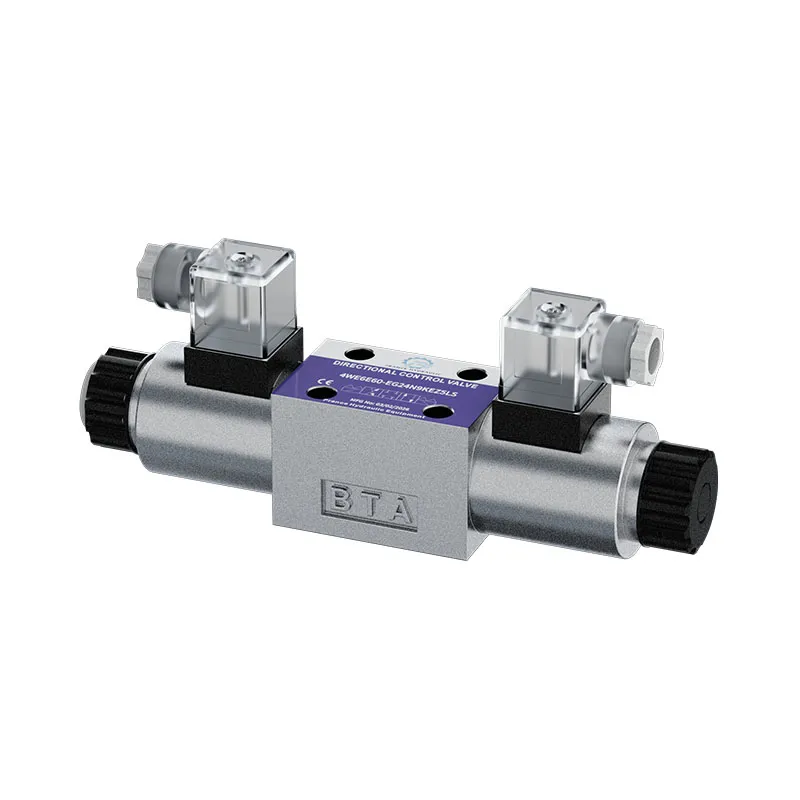
Wenzhou Prance Hydraulic Equipment Co., Ltd.

Hydraulic Solenoid Valve Voltage Drop: Testing 12V and 24V Coils
Hydraulic solenoid valve voltage drop should be checked with the coil connected and commanded under a controlled test condition. Measure the actual voltage across the coil, then locate losses in the supply and return paths. A normal reading at an unplugged connector can hide a weak connection that fails under load. Start by confirming the coil's specified supply type and rating, including whether it uses steady DC, AC, or an electronic current-controlled driver. A 12V or 24V label alone does not define every permissible operating condition or testing method.
Confirm the coil and control arrangement
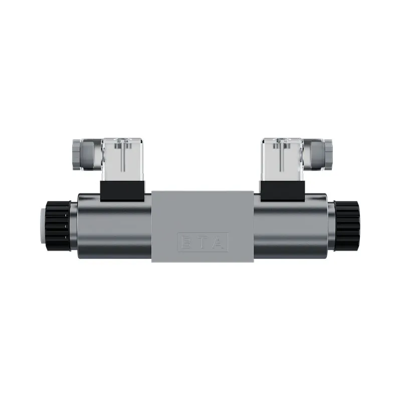
Read the complete coil marking and valve code. Record nominal voltage, AC or DC, duty, electrical connector, and any suppression or indicator circuit. Obtain the coil data and the machine wiring diagram. Do not infer voltage from plug color or assume that a coil supplied with a similar valve has the same electrical rating.
Identify how the controller switches the circuit. Some systems switch the positive supply, some switch the return side, and others regulate current using pulse-width modulation. This determines the measurement points and the meaning of the readings. A general DC meter may show an average of a pulsed signal rather than the driver behavior needed for diagnosis.
Confirm the permitted diagnostic procedure for electronic outputs. Applying an external supply, adding an arbitrary test lamp, or bypassing the driver can damage electronics or command unexpected valve movement. Choose a method suitable for the actual circuit and instrument, with the machine secured against movement.
Why an unplugged voltage reading can mislead
A high-impedance meter draws little current. With the coil disconnected, a corroded contact or damaged wire may still allow the meter to display a plausible voltage. When the coil draws current, the same resistance causes a larger loss and reduces voltage at the coil.
The basic relationship is voltage loss equals current multiplied by resistance for a resistive path. An illustrative 0.5 ohm unwanted resistance carrying 1 A produces 0.5 V loss and dissipates 0.5 W. These values demonstrate the mechanism; they do not establish an acceptable limit for a particular valve circuit.
Indicators require similar caution. A connector LED may illuminate with insufficient coil supply or through a different electrical path. It confirms only what its circuit actually senses. Treat it as an observation and verify voltage across the coil terminals during the relevant command.
Prepare a controlled measurement
Secure the machine and load, establish who controls the command, and use appropriate instruments and approved access points. Live voltage tests require energized electrical circuits and may energize a hydraulic function. Electrical isolation for installing test leads and controlled energization for the measurement should follow the machine's procedure.
Check the meter function and lead sockets before use. Use the appropriate AC or DC voltage range, intact probes, and a method that avoids bridging neighboring pins. Do not place a meter in current mode across a supply. For inaccessible sealed plugs, use an approved breakout arrangement rather than damaging seals with improvised probing.
Record supply voltage at the source, voltage across the connected coil, command state, oil or coil temperature where relevant, and whether the fault is present. Intermittent problems require measurements during the event. A reading taken after the machine has recovered may not explain the earlier failure.
Measure coil voltage and the two loss paths
For a conventional steady-DC circuit, first measure between the coil's two terminals while it is commanded. This captures the voltage available to the coil regardless of which side is switched. Compare with the exact coil's permitted operating range rather than a universal percentage rule.
Next measure the loss along the supply path, between the source supply point and the coil supply terminal. Then measure the return-path loss between the coil return terminal and the source return point. Keep the coil loaded and commanded while using the approved procedure. Interpret switched or electronically controlled sections using the wiring diagram.
Break a high-loss path into sections: fuse connection, relay contacts, harness junction, connector, cable, and return connection. Measure across one section at a time to locate the loss. Replacing a coil before identifying a poor return connection can leave the original fault unchanged.
Interpret common result patterns
This table assumes a conventional steady-DC on/off circuit tested at its permitted command. PWM and current-controlled outputs need their specified diagnostic method. Fluke's voltage-testing material provides measurement background, while the coil's data defines acceptance limits.
| Beobachtung | Possible explanation | Useful next check |
|---|---|---|
| Source voltage falls during command | Supply weakness or excessive shared demand | Measure source behavior during the same event |
| Source stays normal, coil voltage falls | Loss in supply, return, or switched path | Divide the path into sections under load |
| Connector LED lights but coil does not shift | Indicator does not prove adequate coil energy | Measure across the actual coil terminals |
| Voltage changes when harness moves | Intermittent connection or broken conductor | Inspect and test the affected section safely |
| Coil voltage is within its specified range | Fault may be coil, actuation, pilot, or hydraulic | Continue with separate resistance and mechanical checks |
| Meter reading is unstable on electronic output | Pulsed control or output protection | Use the driver's specified diagnostic method |
An example using 12V and 24V circuits
Suppose a steady-DC 24V circuit measures 24.2 V at its source and 21.8 V across the energized coil. Measurements show 1.6 V loss in the supply path and 0.8 V in the return. The total loss is 2.4 V, consistent with the difference between source and coil readings.
This identifies where to investigate, but it does not automatically classify the coil as passing or failing. Compare 21.8 V with its documented operating conditions and observe actuation. A 12V circuit experiencing the same absolute loss has a larger relative reduction, yet acceptance still belongs to the exact coil and machine requirements.
Avoid assuming that one threshold applies to every connector, controller, or cable length. The useful diagnostic question is whether the loaded circuit delivers the specified coil input and where any unwanted loss occurs. Record actual values and conditions instead of writing only low voltage on the service sheet.
Temperature and intermittent failure
A fault may appear only after the coil, connector, relay, or harness becomes warm. Heating can change electrical resistance and expose a marginal connection. Compare cold and hot readings under the same command and preserve the temperature or elapsed-time information.
Inspect connectors for moisture, looseness, damaged seals, overheated contacts, and cable strain. A connector can develop localized resistance while the coil winding remains normal. Any repair should restore the specified sealing and strain relief, not simply make the circuit work temporarily with exposed conductors.
Where the driver shuts down, obtain its diagnostic code and operating conditions. The cause may be excessive current, temperature protection, a short, or command logic rather than supply voltage loss. Do not repeatedly reset the output without identifying why protection is operating.
Keep voltage and resistance tests separate
Voltage-drop testing examines an energized circuit under load. Coil resistance testing uses an isolated, de-energized circuit with stored electrical energy safely addressed. These are different tests. Never use the resistance function on an energized output.
Disconnect the coil as specified so that the controller, suppression diode, indicator, or parallel circuit does not distort the winding measurement. A normal resistance does not prove full actuation, and low coil voltage does not prove a damaged winding. Build the diagnosis from separate electrical and hydraulic evidence.
Fluke's resistance-measurement guidance emphasizes removing power before resistance measurement. NIOSH hazardous-energy guidance adds the machine-level issue: hydraulic pressure and gravity can remain hazardous after electrical power is isolated. Secure the actuator and load before manipulating a connector or valve.
Confirm that electrical recovery restores valve function
After repairing the identified connection or supply issue, repeat source voltage, coil voltage, and path-loss measurements under the original fault conditions. Check hot operation and any simultaneous machine functions that previously triggered the problem. Record the before and after results.
Then verify the actual directional-valve response. Adequate coil voltage does not prove that a spool is free, pilot pressure is sufficient, or work ports connect correctly. Observe the intended movement and stopping behavior under the approved commissioning process, including both coils where the valve uses two solenoids.
Avoid changing hydraulic relief settings to compensate for an electrical fault. Keep the circuit configuration documented and change only what the evidence justifies. If actuation remains unreliable with verified electrical input, investigate the coil, armature, spool, pilot circuit, and hydraulic conditions separately.
Information for a replacement or service request
Provide the valve and coil codes, rated supply, wiring diagram, controller type, command condition, source and coil readings, voltage losses by path, temperature, and observed valve behavior. Identify whether the circuit uses PWM, a suppressed connector, or a current-controlled driver.
For replacement, confirm voltage type, duty, power or current requirements, mounting, connector, suppression, polarity where relevant, and controller compatibility. Similar external appearance or a matching nominal voltage is not enough to prove electrical interchangeability. Keep the complete configuration traceable through the quotation and commissioning records.

Häufig gestellte Fragen
Why does my meter show 24V with the coil unplugged?
A lightly loaded meter may show voltage through a poor connection that cannot supply the coil properly. Test the permitted connected circuit under command and measure losses in the supply and return paths.
Does an illuminated plug prove the coil is powered correctly?
No. It proves only the indicator's electrical condition. Measure across the coil and compare with the exact operating requirements while observing actual valve response.
Is a specific voltage-drop percentage acceptable for every coil?
No universal value should replace the selected coil and controller requirements. Record actual loaded voltage and path losses, then compare them with the documented operating range.
Can I use a DC meter on a PWM driver?
A meter may display an average that does not establish the waveform or controlled current. Follow the driver and instrument diagnostic instructions for pulsed outputs.
Can I measure resistance while commanding the valve?
No. Resistance measurement requires the appropriate de-energized and isolated setup. Address stored energy and secure the machine before disconnecting or testing the coil.
Related products and engineering guides
For a duty-based enquiry, review Wegeventil 4WE. Confirm the complete ordered configuration, drawings, operating conditions and integration responsibilities with the supplier. Related resources: hydraulic valve range, solenoid valve fundamentals, coil failure diagnosis, valve connector identification, Hydraulic Directional Valve Internal Leakage Test, Hydraulic Solenoid Coil Resistance Test: Ohms and Temperature.
University lesson: directional-control valves
This NPTEL-NOC IITM university lecture explains the hydraulic connections and switching role of a directional-control valve. It provides valve-function background; the electrical measurements and connector selection in this guide require their own component documentation.

Technical references
- NPTEL: Grundlagen der industriellen Ölhydraulik und Pneumatik
- NIOSH: Verletzungen durch gefährliche Energie verhindern
- Fluke: electrical tester applications and loaded circuit checks
These sources provide technical, educational and safety context. Example calculations are illustrative, and neither their inputs nor another manufacturer’s component data establish a Prance product rating or brand affiliation.