Wenzhou Prance Hydraulic Equipment Co., Ltd.

Orbital Motor Spool Valve vs Disc Valve: Design and Duty Differences
An orbital motor spool valve vs disc valve comparison concerns how the motor distributes pressure and return flow to its working chambers. A spool-valved design uses a cylindrical rotary distribution interface; a disc-valved design uses a face-type distribution interface. Both must keep the flow connected to the correct chambers as the displacement group moves. The valve label alone does not determine starting torque, low-speed smoothness, efficiency or permissible pressure. Select from the complete motor’s performance curves, construction and operating limits, rather than assuming every disc-valved motor is automatically better than every spool-valved motor.
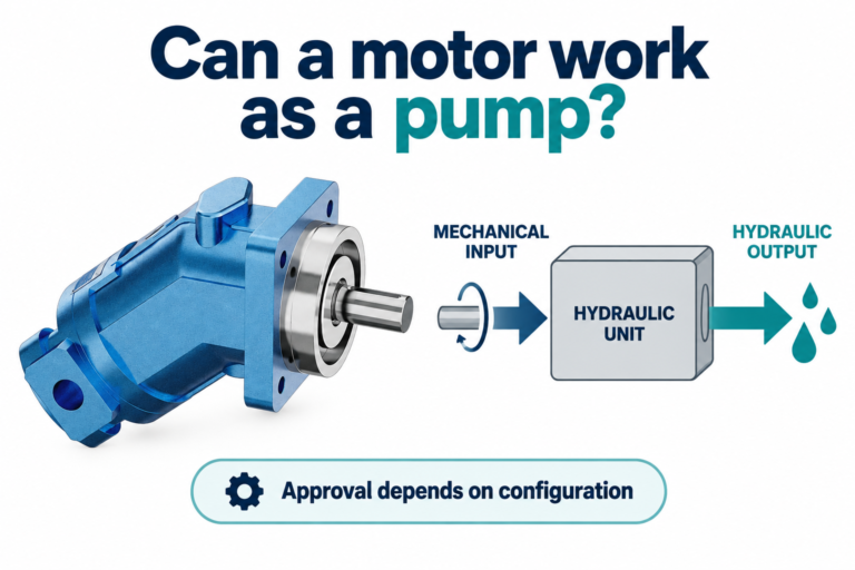
This article compares the two distribution approaches and the evidence needed for a replacement. It does not repeat a tooth-by-tooth commutation lesson. The illustrated Prance motor is a real catalog reference whose product description identifies disc valving; its exterior does not reveal internal clearances or establish ratings for a specific order.
Separate the distributor from the displacement group
An orbital motor contains working chambers whose volumes change as the rotor moves within its surrounding structure. The distributor connects expanding chambers to supply and contracting chambers to return at the appropriate points in the cycle. Pressure acting through the displacement mechanism produces torque at the output shaft.
The displacement group and distributor are different parts of that explanation. Terms such as gerotor or roller-type orbital construction describe the working geometry, while spool or disc valving describes the distribution approach. Neither phrase alone specifies the bearing system, shaft-seal capability, optional brake or external load capacity.
That distinction helps when comparing quotations. Two motors with similar displacement and mounting dimensions may use different distributors, bearings and seals. Conversely, two disc-valved motors may have very different continuous-duty envelopes. Compare the actual configurations, not a family name or a photograph that happens to look familiar.
What spool valving means in this comparison
In a spool-valved orbital motor, a cylindrical rotating distribution surface and matching passages route flow through the working cycle. In some designs distribution is integrated with the output shaft; exact construction varies. The relevant sealing and leakage interfaces therefore depend on the specific motor’s shaft, bore, grooves and support arrangement.
This architecture can provide a compact package, but compactness is not a numerical performance rating. Its useful operating envelope depends on clearances, materials, lubrication, pressure balance and the rest of the motor. A statement that one construction is economical or simple does not prove it will meet a demanding low-speed duty.
Wear or contamination at a distribution interface may increase internal leakage or disturb consistent operation. However, excessive leakage can also occur elsewhere in the displacement group. Do not diagnose a worn spool solely because a motor needs more flow to maintain speed. Compare controlled test results with the service documentation.
What disc valving changes
In a disc-valved motor, distribution occurs across a rotating face-type interface that opens the appropriate passages through the cycle. The drive arrangement must keep the distributor synchronized with the displacement mechanism. Some designs use pressure balancing or other features to manage the forces across that interface; these are model-specific features, not a universal promise.
The face interface creates its own requirements for flatness, contact condition, cleanliness and lubrication. Scoring or damage can create unwanted leakage paths. It is therefore misleading to call a disc valve immune to contamination, or to assume a more sophisticated distributor allows relaxed oil cleanliness.
Disc valving is often encountered in motors intended for demanding low-speed, high-torque service. Nevertheless, only the selected motor’s curves and limits establish its capability. Do not transfer a competitor’s pressure rating, efficiency claim or minimum speed to the Prance reference motor merely because both use a disc distributor.
Compare the complete motor rather than the label
The following table is a qualitative selection framework based on the linked university material and the operating principles described in the product documentation. It intentionally contains no assumed model ratings. Confirm construction details and numerical limits with the supplier for the complete ordering code.
| Comparison point | Spool-valved approach | Disc-valved approach | Anzufordernde Beweismittel |
|---|---|---|---|
| Distribution interface | Cylindrical rotating interface | Rotating face interface | Sectional or service description for the exact motor |
| Synchronization | Depends on shaft and distributor arrangement | Depends on disc drive and timing arrangement | Approved assembly and timing information |
| Interner Druckverlust | Depends on working clearances and wear paths | Depends on face condition, balancing and other clearances | Curves or approved test data at relevant conditions |
| Low-speed operation | Cannot be predicted from the valve name alone | Cannot be predicted from the valve name alone | Minimum stable speed and starting-torque information |
| Replacement fit | Dimensions and construction must be verified | Dimensions and construction must be verified | Complete code, shaft, flange, ports and drain requirements |
A quotation should answer the last column. If it only states “disc valve, high efficiency,” the comparison is incomplete. Ask which operating point supports that claim and whether it applies continuously or only intermittently.
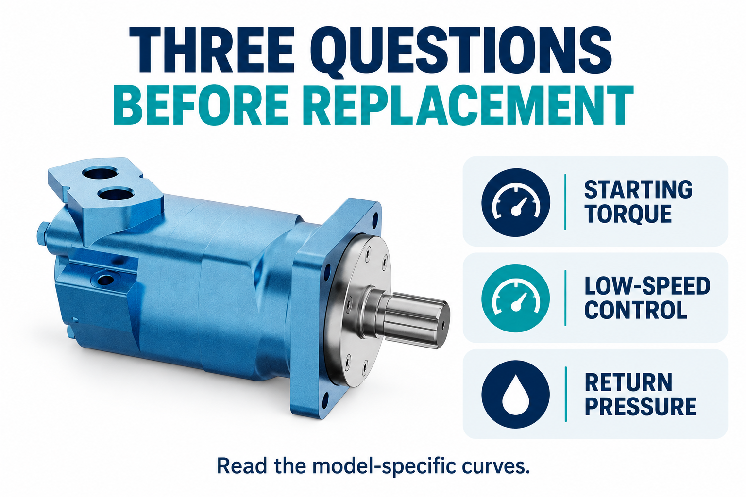
Compare starting torque at the actual load
Starting torque is the torque available when the motor begins to turn under the stated conditions. Running torque and theoretical torque are different quantities. A motor that can sustain a load once moving may still struggle to start that same mechanism, especially when friction, load position or pressure availability changes.
For a displacement motor, theoretical torque in newton-metres can be estimated as pressure difference in bar multiplied by displacement in cubic centimetres per revolution, divided by approximately 62.8. A hypothetical motor with 200 cubic centimetres per revolution and a 100 bar pressure difference has about 318 N·m theoretical torque. This calculation assumes no mechanical loss; it is not starting torque or a catalog rating.
Use the pressure difference across the motor, not simply the pump gauge pressure. Return-side pressure reduces the available differential. Line and control-valve losses can also reduce the pressure reaching the inlet. Check the worst load position and the supply available during startup before deciding that a distributor change will solve insufficient torque.
Low-speed smoothness needs its own evidence
Low average speed does not guarantee smooth motion. Torque ripple, friction, leakage, load inertia and control behavior all contribute to what the driven equipment actually does. The orbital working cycle itself produces changing chamber forces, and the distribution arrangement is only one part of that system.
Request minimum stable speed or low-speed performance information at the intended pressure, fluid viscosity and load. If a test is needed, define speed variation and the measurement method instead of relying on a description such as “runs smoothly.” A short unloaded rotation test cannot establish loaded performance throughout a production cycle.
Also separate a motor problem from a control problem. A flow-control valve operating unstably, air in the circuit or a sticking mechanical load can produce irregular motion. Replacing a spool-valved motor with a disc-valved one may leave those causes untouched. Establish the symptom and operating conditions before specifying a new architecture.
Follow leakage and heat through the whole motor
Internal leakage allows some supplied flow to pass without contributing fully to useful displacement. The result may include lower speed for the same inlet flow or increased flow demand to maintain speed. Pressure losses and friction also convert hydraulic power into heat. Neither symptom uniquely identifies the distributor as the damaged component.
Compare leakage or efficiency at matched temperature, viscosity, speed and pressure. Warm oil can reveal a problem that is less apparent during a cold test. A catalog curve at one fluid condition should not be treated as an exact prediction for another. Use the supplier’s approved test method and allowable limits.
Where an external case drain is specified, its flow may support diagnosis, but it is not automatically equal to all internal leakage. Internal routing differs between motor designs. Do not block a required drain or add an arbitrary restriction to measure it. Confirm both the test arrangement and permissible case pressure before connecting instruments.
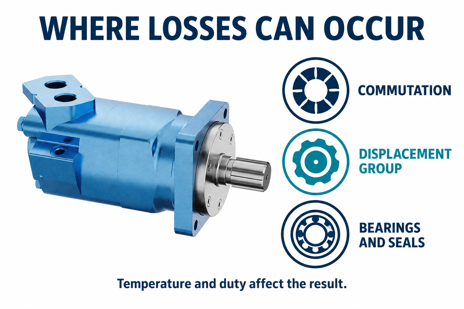
Return pressure and shaft seals can decide the replacement
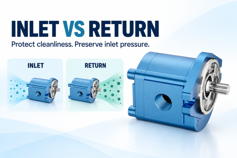
The motor outlet may not discharge directly to an unpressurized tank. Reversing valves, long lines, filters and series circuits can produce return pressure. Some operating modes can also place either work port under high pressure. Review the maximum pressures at both ports and the case under every intended direction and transient.
Shaft-seal capability is a separate requirement from the distributor’s pressure capability. A motor can be acceptable for a given working pressure difference while still requiring a particular drain arrangement to protect its seal. Do not infer seal limits from a claim that the motor is “high pressure.”
The mechanical connection matters too. Radial load, axial load, overhung distance and mounting stiffness must match the shaft and bearing arrangement. A physically interchangeable flange does not prove that a motor can accept the same wheel, pulley or sprocket load. Obtain the relevant load information for the actual configuration.
Keep timing and service work model-specific
Correct distributor timing is essential, but assembly instructions cannot be generalized from another motor family. Different drive links, indexing features and port arrangements may require different procedures. A parts diagram or online demonstration is not sufficient authority to improvise a timing method for the pictured product.
If disassembly is authorized, follow the approved cleanliness, inspection, assembly and test instructions. Inspect the distributor and displacement group together as required. Replacing one visibly scored surface may not restore performance if contamination has damaged other running clearances or the underlying cause remains in the circuit.
Isolate hydraulic and mechanical energy before service, secure suspended or gravity-driven loads and account for retained pressure. The NIOSH resource linked below explains hazardous-energy prevention principles. A stopped shaft does not prove that the system is safe to open, and a motor is not an independent holding brake unless its documented configuration provides that function.
Prepare a replacement request that can be checked
Send the complete existing code and the required displacement, starting torque, operating speed range and duty cycle. Include pressure at both work ports, fluid identity, temperature range, case-drain requirements and external shaft loading. Provide shaft, flange and port dimensions from drawings rather than an approximate visual match.
Ask the proposed supplier to identify the distribution architecture and explain which performance evidence supports the recommendation. Request continuous and intermittent limits separately, together with relevant curves and fluid conditions. Confirm rotation conventions and the complete configuration before placing an order.
The useful conclusion may be to retain the existing type, choose a different motor within the same architecture or change architecture after a documented comparison. The goal is a motor that starts, runs and survives in the real machine. A spool-versus-disc label is the start of that comparison, not its final answer.
Häufig gestellte Fragen
Is a disc-valved orbital motor always more efficient?
No. Efficiency depends on the complete design and operating point. Compare current curves at matched displacement, pressure, speed, temperature and fluid viscosity. A broad statement about an architecture cannot replace evidence for the selected motor.
Is spool valving the same as a directional spool valve?
No. Here it describes the motor’s internal rotary distribution interface. An external directional valve commands flow to and from the motor. Both route fluid, but they occupy different positions and perform different jobs within the system.
Can the valve type be identified from the motor’s exterior?
Not reliably. Verify the full product code and documentation. Similar housings may contain different options, and a photograph does not reveal distribution clearances, pressure balancing or the internal drain arrangement.
Will changing to disc valving fix low-speed jerking?
It might change performance, but the symptom alone does not establish the cause. Check loaded low-speed capability, controls, fluid condition, air and mechanical friction. Compare the candidate motor under the actual duty before treating a construction change as the remedy.
What information matters most for a replacement inquiry?
Provide the complete code, starting and running load, speed range, duty, pressures at both ports, drain conditions and fluid information. Add shaft, flange and external-load details. Require model-specific performance evidence alongside any proposed spool or disc designation.
Produktdaten und entsprechende technische Ressourcen
The Hydraulic Orbital Motor BMT catalog exterior is used as the real product reference in these explanatory images. It does not establish the approved service method, optional construction, or operating limits for an individual order. Confirm the complete code and its documentation. Related resources: Hydraulischer Gerotor-Motor BMT, Hydraulikmotor-Palette, Orbit Motor Valve Timing: Gerotor Commutation Explained, Radialkolbenmotor – Funktionsprinzip: Drehmoment bei niedriger Drehzahl.
Sources and limits of this guide
The university resource supports the component operating principles. NIOSH supplies hazardous-energy prevention context; exact machine isolation and component service requirements still need their approved procedures. Sources explain general operating principles, not performance ratings or optional features of the pictured catalog component.
- NPTEL: Grundlagen der industriellen Ölhydraulik und Pneumatik
- NIOSH: Verletzungen durch gefährliche Energie verhindern
- DIN Media: DIN EN ISO 4413, hydraulic fluid power safety (standard overview)
University lesson: operating principles
NPTEL-NOC IITM presents 6.3 – Hydraulic Motors. The lesson supports the motor operating principles used in the engineering discussion; it is not a model-specific repair, storage, or installation approval.