Wenzhou Prance Hydraulic Equipment Co., Ltd.

Hydraulic Solenoid Coil Resistance Test: Ohms and Temperature
A hydraulic solenoid coil resistance test checks the winding's electrical resistance with the circuit de-energized and the coil isolated from other electrical paths. Compare the measured value with the exact coil's specification at a stated temperature. There is no universal correct resistance for all 12V or 24V hydraulic coils. An open winding, unusually low resistance, or a meaningful departure from the proper reference can support a diagnosis, but a normal reading does not prove that the valve shifts correctly. Follow the machine's isolation procedure before disconnecting or testing a coil.
Identify the exact coil before measuring
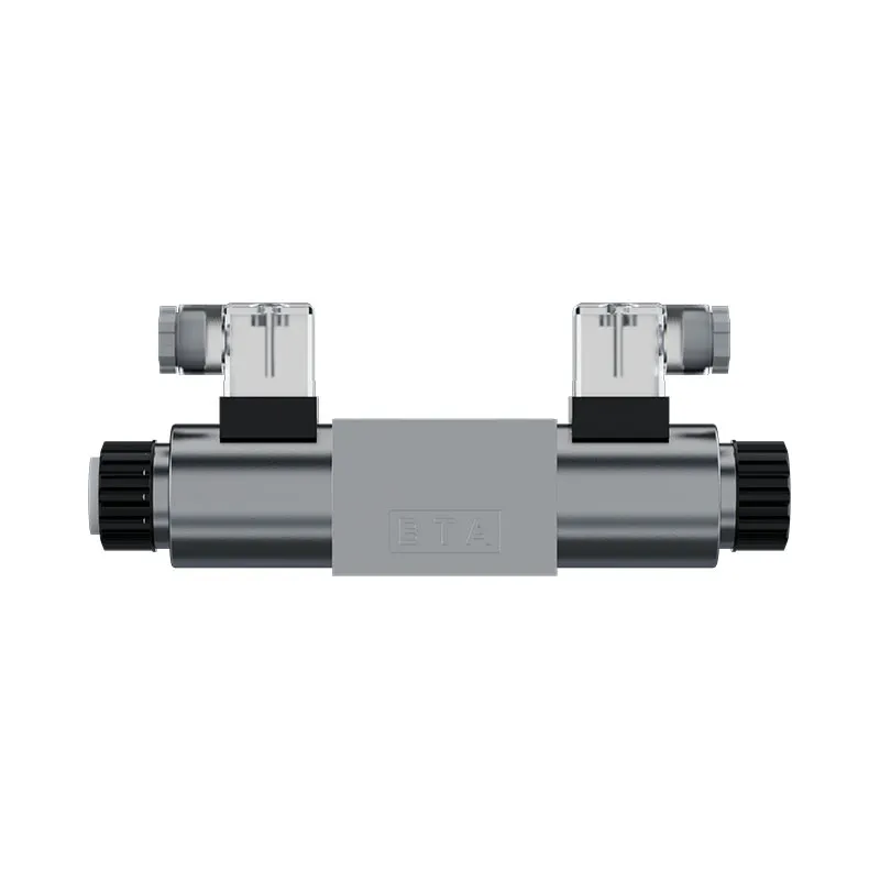
Record the valve code, coil code, nominal voltage, AC or DC supply, duty, rated power or current, and connector option. Two coils carrying the same nominal voltage can have different resistance because their winding and power requirements differ. A replacement selected only from the voltage label may overload a driver or produce inadequate actuation.
Find the manufacturer's resistance value, tolerance, and reference temperature if provided. If these are unavailable, identify a verified identical coil and document its condition before using it as a comparison. A different valve size or similar-looking winding is not an adequate reference.
Check for an indicator, diode, rectifier, surge suppressor, or integrated electronics in the connector or coil. These can change the meter reading, particularly when probe polarity is reversed. Determine whether the intended test measures a bare winding or an assembly containing additional circuitry.
Isolate electricity and machine energy
Remove electrical power and verify the relevant circuit is de-energized using the approved method. Address stored electrical energy before selecting the resistance function. Fluke's resistance-measurement guidance states that power must be removed before the test; an energized resistance measurement can damage equipment and produce invalid results.
The hydraulic machine also needs isolation. Secure or support the load, account for trapped pressure, and prevent automatic commands or gravity-driven movement. Disconnecting a plug does not necessarily remove hydraulic or mechanical stored energy. Use the machine's documented procedure rather than treating the coil as an isolated bench component while it remains installed.
Allow hot parts to reach a suitable condition for handling, and record temperature for the measurement. Do not remove or energize a coil separately from its intended magnetic assembly unless the manufacturer's test procedure permits it. Some assemblies depend on that installation for correct current and thermal behavior, especially with AC coils.
Choose and check the meter
Use an intact digital multimeter with a suitable resistance range and the correct test-lead connections. Check the meter and lead condition on a known reference or through the instrument's recommended verification. Poor probe contact can make a sound coil appear open or unstable.
At low resistance, lead resistance can be significant relative to the winding. Touch the probes together and record or compensate for the lead contribution using the meter's supported method. At higher values, avoid touching exposed probe contacts in a way that adds an unintended parallel path.
A continuity beep is not a complete resistance test. The threshold for that signal depends on the instrument, and a winding can be continuous while outside its correct resistance range. Record the numerical reading, range, reference, and temperature rather than writing only continuity OK.
Measure the isolated winding
Disconnect the approved electrical interface and identify the winding terminals from the coil drawing. Where the connector contains a diode or indicator, separate it from the winding as the instructions permit. Do not assume that every visible pin belongs to the same winding path.
Place the probes on clean, secure terminals and allow the reading to settle. Record the value, temperature, probe arrangement, and whether additional components remain connected. If the reading changes, check probe contact and the meter before attributing instability to the winding.
Where integrated electronics cannot be separated, follow the assembly's specific procedure. Reversing probes may change the reading through a semiconductor circuit. Do not convert that behavior into an unsupported claim of winding damage, and do not apply a high-voltage insulation test to electronics without explicit suitability.
Interpret the result carefully
The table below is a qualitative diagnostic aid. Numerical acceptance limits come from the exact coil, not from a generic hydraulic-valve resistance chart.
| Resistance observation | Possible meaning | Confirmation needed |
|---|---|---|
| Open or out-of-range display | Open winding, bad contact, wrong terminals, or meter range issue | Verify meter, probes, connection, and coil terminal identification |
| Very low value relative to specification | Incorrect coil, damaged winding, or additional electrical path | Isolate the winding and compare with the correct reference |
| Higher value while hot | Temperature effect or contact resistance | Record temperature and retest under comparable conditions |
| Stable value within specification | Winding DC resistance is consistent with the reference | Continue with supply, actuation, and hydraulic checks |
| Different readings with reversed probes | Connected diode or electronic circuit | Check the assembly schematic and specified method |
| Intermittent open reading | Connection fault or winding break affected by movement or heat | Use a controlled test without damaging the assembly |
Why temperature changes resistance
The resistance of a copper winding increases as temperature rises. Consequently, a hot coil can read higher than an identical cold coil even when both are sound. Document the temperature or allow both to reach a comparable condition before drawing a conclusion.
For a simplified copper example near room temperature, using the standard-copper coefficient in NIST copper wire tables, resistance can be estimated as R at temperature T equals R at 20 degrees C multiplied by one plus approximately 0.00393 times the temperature rise from 20 degrees C. This is an approximate material relationship, not a manufacturer tolerance or a correction for every assembled coil.
If an illustrative winding is 30 ohms at 20 degrees C, the simplified estimate at 80 degrees C is about 37.1 ohms. A measured 37 ohms under that hot condition is therefore not automatically evidence of damage. Use the coil's own reference conditions, winding material, and specification for an actual acceptance decision.
The internal winding temperature may differ from the outside housing temperature. A surface reading can provide useful context but does not justify a highly precise correction to an unknown internal temperature. Where accuracy matters, use the specified test condition rather than assuming the two temperatures are equal.
Using voltage and power as a rough cross-check
For an ideal steady-DC resistive load, resistance equals voltage squared divided by power. An illustrative 24V, 20W winding would imply about 28.8 ohms at the condition represented by those ratings. An equivalent 12V, 20W example implies about 7.2 ohms.
These examples show why equal power does not mean equal resistance at different voltages. They are not a catalogue table for hydraulic coils. Rated power may relate to a defined hot operating condition, and actual cold resistance can differ. Obtain the proper winding specification before marking a real result as passing or failing.
Do not apply the same simple calculation to infer AC winding current from DC resistance alone. AC impedance includes inductive effects and depends on the magnetic assembly and operating state. PWM or current-controlled systems also require their driver's specified operating checks rather than a steady-DC assumption.
What resistance cannot prove
A winding can have a plausible DC resistance yet fail under heat, have an insulation problem, or provide inadequate magnetic actuation. Turn-to-turn damage may not create an obvious change on a basic meter. A resistance check is one part of diagnosis, not a certificate of complete electrical health.
It also cannot establish spool freedom, pilot pressure, mechanical alignment, or correct hydraulic connections. An audible click does not prove full valve travel. Confirm electrical supply under command and then check the valve's actual flow function through an approved machine test.
Insulation testing is a separate procedure requiring appropriate voltage and acceptance criteria. Integrated electronics and suppression devices can be damaged by unsuitable instruments. If that assessment is needed, use the coil manufacturer's permitted method or refer the assembly to a competent service provider.
Investigate why the coil failed
Before replacing an apparently failed winding, examine the supply type, loaded voltage, command duration, heat exposure, connector condition, and driver compatibility. A wrong voltage or unsuitable duty can damage the next coil as well. Verify whether the installed connector adds suppression that the controller expects.
For AC assemblies, incomplete magnetic seating can change operating current and heating. Mechanical obstruction or incorrect assembly therefore deserves attention alongside the electrical supply. Do not energize a removed AC coil as a casual test; follow the specific equipment instructions.
Inspect moisture entry, cable strain, damaged seals, and terminal heating. A connector fault can resemble a winding fault or create a thermal problem at the interface. Replace or repair the identified cause and restore the required sealing, pin connections, and strain relief.
Record and verify the repair
Keep the original measured value, reference source, temperature, meter, and isolation method. Record the replacement code and its confirmed electrical options. This creates a useful maintenance comparison and prevents future technicians from applying the wrong reference to a different coil.
After restoring the circuit, verify actual coil voltage or controlled current using the approved method. Confirm that the valve shifts and returns as intended, including hot operation and the original failure conditions. Check stopping and load control at the machine level rather than treating a new winding reading as the end of commissioning.
For a supplier enquiry, include the complete valve and coil markings, supply and controller type, connector and suppression option, resistance readings, temperatures, symptom history, and operating cycle. Prance's valve range can provide a starting point, but the replacement configuration must be verified against these requirements.

Preguntas frecuentes
What resistance should a 24V hydraulic coil have?
There is no single correct value. Winding power, construction, temperature, and additional circuitry affect the result. Compare with the exact coil's specified resistance under its stated conditions.
Does a continuity beep mean the coil is good?
It shows continuity within the meter's threshold, not complete coil health. Record numerical resistance and compare with the correct specification, then check electrical input and valve function separately.
Why is the hot resistance higher?
Copper winding resistance rises with temperature. Compare like temperatures or use the manufacturer's stated test condition. Surface temperature does not necessarily equal the internal winding temperature.
Can a normal resistance coil still fail to shift the valve?
Yes. Supply loss, insulation problems, magnetic or mechanical faults, inadequate pilot conditions, and spool obstruction can remain. Continue diagnosis using electrical and hydraulic evidence.
Can I test resistance without disconnecting the controller?
Only if the documented test method supports that arrangement. Parallel electronics and suppression components can distort the result. Remove power, verify isolation, and follow the approved winding measurement procedure.
Related products and engineering guides
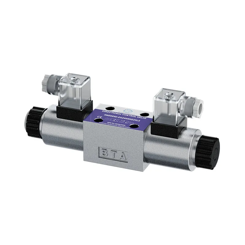
For a duty-based enquiry, review Válvula direccional 4WE. Confirm the complete ordered configuration, drawings, operating conditions and integration responsibilities with the supplier. Related resources: hydraulic valve range, solenoid valve fundamentals, coil failure diagnosis, valve connector identification, Hydraulic Directional Valve Internal Leakage Test, Hydraulic Solenoid Valve Voltage Drop: Testing 12V and 24V Coils.
University lesson: directional-control valves
This NPTEL-NOC IITM university lecture explains the hydraulic connections and switching role of a directional-control valve. It provides valve-function background; the electrical measurements and connector selection in this guide require their own component documentation.

Technical references
- NPTEL: Fundamentos de la hidráulica y la neumática industriales
- NIOSH: prevención de lesiones por energía peligrosa
- Fluke: resistance measurement and instrument safety
- NIST: copper wire tables and temperature coefficient
These sources provide technical, educational and safety context. Example calculations are illustrative, and neither their inputs nor another manufacturer’s component data establish a Prance product rating or brand affiliation.