Wenzhou Prance Hydraulic Equipment Co., Ltd.

Minimum Pump Displacement: Residual Flow and Standby Losses
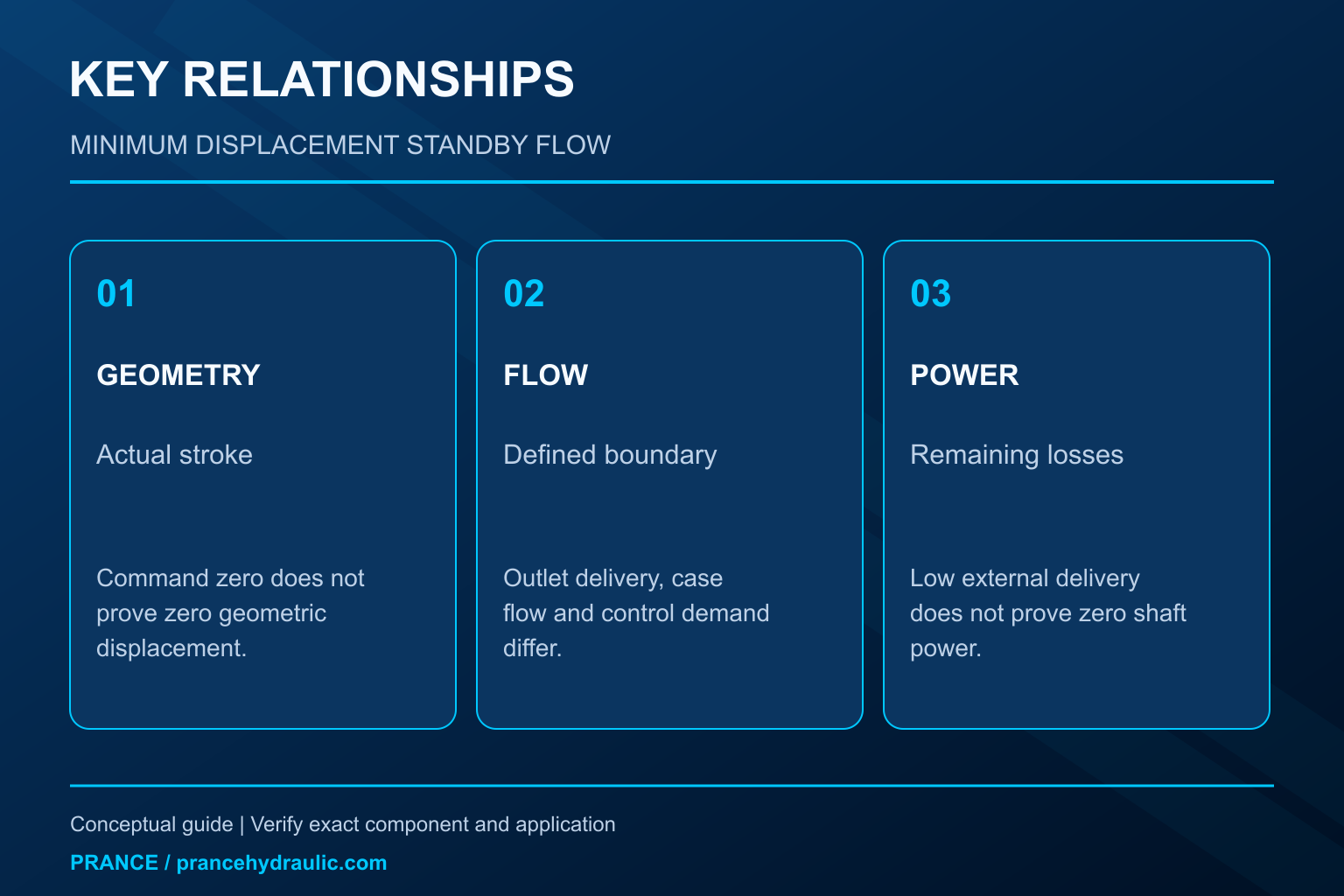
Hydraulic pump minimum displacement leakage is best understood by separating geometry from measured flow. A variable pump can approach its minimum displacement while still consuming power and circulating oil internally. The small stroke needed to replace leakage, oil used by the control, and flow leaving the pressure outlet are different quantities. A near-zero command does not establish zero shaft power, and a warm case does not by itself prove a worn pump. Before adjusting anything, identify the control variant, the measurement boundary, and the conditions under which the manufacturer defines minimum displacement.
This guide concerns residual flow and losses when a variable-displacement pump is destroked. It does not provide a compensator adjustment procedure or a universal acceptance value for an A10VO pump.
What minimum displacement actually describes
Geometric displacement is the volume that the pumping mechanism would move per shaft revolution at a particular setting. It is a geometric quantity, normally stated in volume per revolution. At a given shaft speed, multiplying displacement by speed produces theoretical flow. Real delivery differs because oil escapes through operating clearances and because some arrangements require control oil.
Minimum displacement is a limit of the particular mechanism and control arrangement. It may be governed by a mechanical stop, the control equilibrium, or the application’s permitted operating range. It should never be inferred solely from the lowest command value displayed on a machine screen. Electrical zero, hydraulic control balance, and the physical displacement position may not coincide.
The HAWE operating instructions linked below illustrate why minimum-displacement and control requirements must be read for the exact pump. They do not establish a setting or operating permission for a Prance product. For a replacement purchase, obtain the ordered control code and its approved documentation before assuming that two similar housings have identical standby behavior.
Why a pressure-compensated pump still strokes at standby
When demand falls, a pressure compensator reduces displacement as outlet pressure approaches its setting. A blocked external actuator circuit can therefore coexist with a rotating pump maintaining pressure. Any oil leaving the pressurized volume through permissible leakage or a required control path must be replenished if pressure is to remain stable.
That replenishment requires some pumping action. A pump that is maintaining pressure is consequently not equivalent to an ideal, loss-free mechanism frozen at exactly zero stroke. The equilibrium depends on speed, pressure, fluid condition, and the actual control arrangement. The pump may move slightly as the compensator balances forces and replaces lost oil.
A small amount of measured outlet flow may also feed a pilot circuit or an external accessory. Calling that flow internal wear leakage would be a boundary error. Trace the circuit and establish where the meter is located before interpreting the reading. The same machine can show different numbers at the pump outlet, the actuator branch, and the reservoir return without any instrument being defective.
Keep the three flow quantities separate
| Quantity | What it represents | Useful check | Common interpretation error |
|---|---|---|---|
| Theoretical displacement flow | Shaft speed multiplied by actual geometric displacement | Use a known displacement position and actual speed | Treating the command as a measured stroke |
| Delivered outlet flow | Net flow crossing the chosen pressure-outlet measurement point | Identify every branch downstream and upstream of the meter | Calling every low flow reading a pump fault |
| Case and control flow | Oil leaving through drain or control routes permitted by the design | Read the exact drain and control diagram | Assuming all drain flow is wear leakage |
| External standby demand | Flow taken by pilot circuits or other consumers | Isolate only through approved machine procedures | Blaming the pump for an open downstream path |
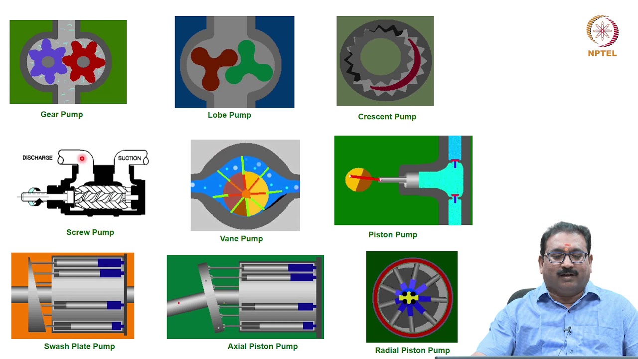
This is a qualitative diagnostic table, not a product parameter table. The NPTEL course provides the general displacement-machine background; actual ports, flow paths, and allowable values come from the pump and machine documents. Do not disconnect a case drain to discover what it does. An interrupted or restricted drain can create damaging case pressure.
A measurement boundary changes the conclusion
Consider a meter installed at the pump outlet before a branch that feeds both a control circuit and an actuator valve bank. Its reading includes both branches. Move the meter into the actuator branch and the result excludes the control demand. A reduction in measured flow after that move says nothing by itself about pump efficiency.
Likewise, a case-drain reading can include intentional control flow or other permitted contributions, depending on the design. Some circuits route external drains separately; others combine returns. A shared hose is not a reliable measurement of one pump’s internal leakage until its connections have been verified against the schematic.
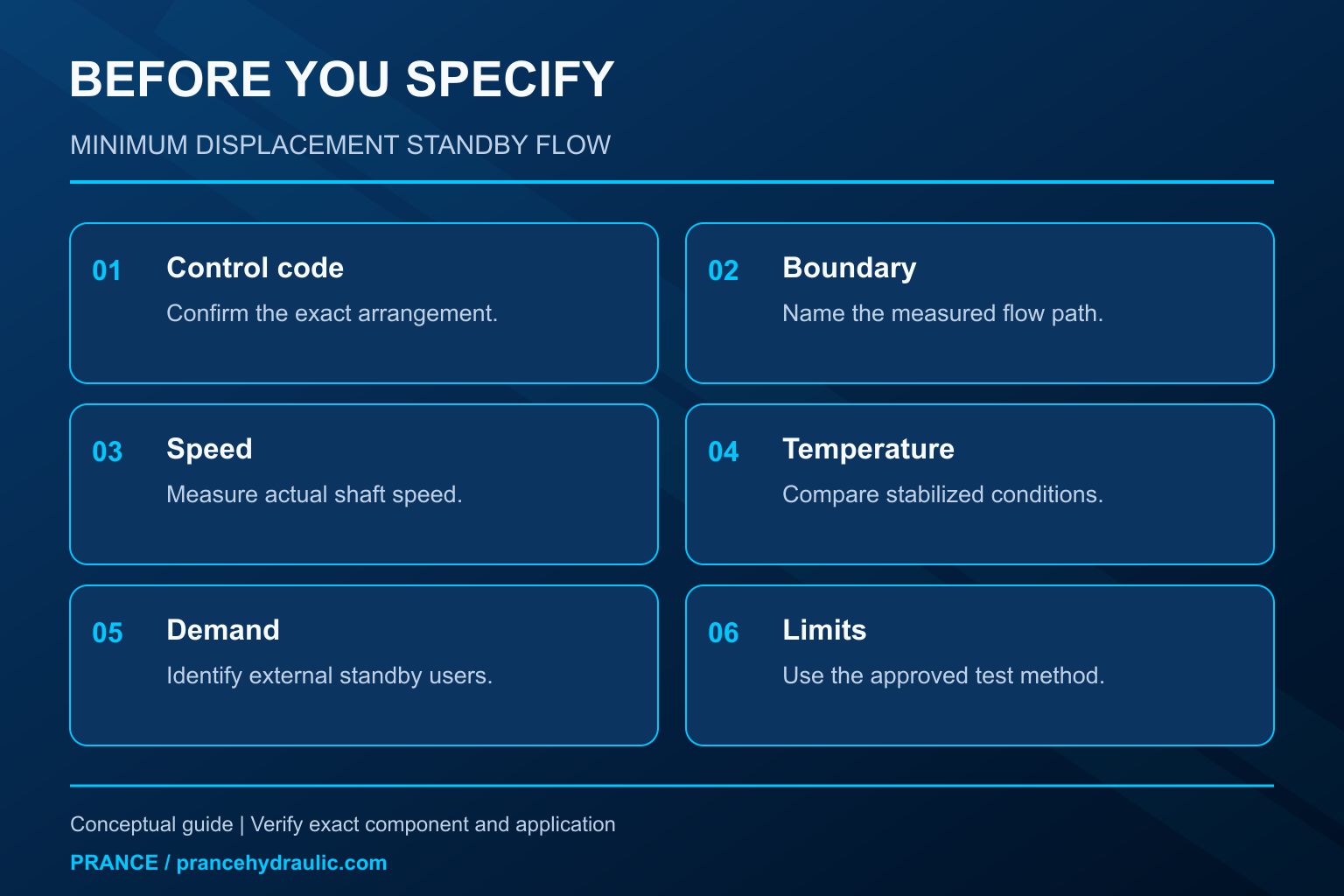
Define the boundary in a simple sentence before testing: for example, net pump outlet flow upstream of all external branches, or individual pump drain flow at a documented operating condition. Add shaft speed, outlet pressure, fluid temperature, and the control state. Those details make a repeated measurement comparable without pretending that one reading can identify every internal loss.
Standby heating is an energy question
High pressure combined with a small flow can still produce meaningful heat. For steady hydraulic power in common metric units, pressure difference in bar multiplied by flow in litres per minute and divided by 600 gives kilowatts. The pressure difference and flow must describe the same path. This relation is a power estimate, not a complete pump-loss model.
As a hypothetical example, a path carrying 2 L/min across 180 bar corresponds to 0.6 kW. A second path carrying 4 L/min across 20 bar corresponds to about 0.13 kW. These values are invented calculation inputs, not expected leakage or ratings for any Prance pump. They show why temperature alone cannot tell whether the main issue is a small high-pressure loss or a larger low-pressure circulation path.
Total shaft input also includes mechanical friction, fluid shearing, and control-related losses. Multiplying outlet pressure by outlet delivery misses losses that do not cross that measurement boundary. Conversely, multiplying outlet pressure by the entire reservoir return can overstate a loss if part of the return never experienced that pressure difference. Use the formula only after drawing the energy boundary.
Distinguish normal replenishment from an abnormal condition
A meaningful comparison uses the same pump configuration at matched speed, pressure, temperature, and control state. Compare with an approved baseline or manufacturer data that describes those conditions. A trend measured cold on one day and hot on another can reflect changed viscosity rather than a new clearance problem.
First establish that the external circuit is actually in the intended standby state. An energized directional valve, a leaking actuator circuit, an intentionally open bleed, or an incorrectly connected pilot line can all create demand. The pump may be responding correctly to a system that is asking for more oil than expected.
Next compare pressure stability, outlet delivery, individual drain behavior where approved, and input power if a suitable instrument is available. Rising drain flow under matched conditions may support an internal-loss investigation, but it is not a stand-alone diagnosis. Record whether the reading is steady or oscillating. An unstable control can produce a very different problem from steady leakage even if their average temperatures look similar.
Do not force the pump toward zero to remove heat
A minimum-displacement stop is not a general-purpose energy-saving adjustment. Reducing it can alter permitted control behavior or leave the pump unable to satisfy required replenishment and auxiliary demand. Increasing it can create unnecessary flow and heating or change how the system reaches pressure cutoff. The correct setting belongs to the approved pump and machine configuration.
A pressure compensator also does not replace the system’s required overpressure protection. Never test whether the pump can safely limit pressure by disabling protective devices. Follow the machine’s isolation, depressurization, and verification procedure before moving instruments or opening lines. Stored pressure can remain after the drive stops.
If an undocumented adjustment has already occurred, preserve the present setting and evidence rather than guessing the original position from the number of turns. Obtain the control documentation and an authorized restoration procedure. A stable pressure reading after an improvised change is not proof that all transient, thermal, or fault conditions remain protected.
Decide whether the next action belongs to the pump or circuit
If standby outlet flow is higher than expected but individual pump losses remain within an approved reference, investigate downstream demand. If a pressure signal changes when another function is enabled, review the pilot and remote-control arrangement. If input power is high with low external delivery, distinguish control losses, mechanical losses, and measurement errors before specifying a replacement.
For the Prance Variable Displacement Pump OEM A10VO 31 Series, the relevant purchasing question is whether the complete control and installation requirements match the machine. The product category establishes relevance to variable displacement; it does not demonstrate that the supplied variant has a particular minimum stop, remote pilot connection, or standby loss figure.
A useful supplier request includes the complete model code, control diagram, required pressure and speed range, fluid and temperature, and a clearly bounded flow measurement. Ask for the permitted standby condition and the method for evaluating it. This creates an actionable review instead of asking for an unsupported guarantee that the pump will deliver exactly zero flow.
Preguntas frecuentes
Does zero commanded displacement mean zero shaft power?
No. The command does not prove actual geometric position, and a rotating machine can consume power through friction, fluid shearing, control operation, and pressure-maintaining replenishment. Evaluate the actual control state and measurement boundary.
Can I calculate leakage by subtracting outlet flow from rated maximum flow?
No. Rated maximum flow may refer to another speed, displacement, pressure, and fluid condition. Leakage comparisons require theoretical flow at the actual displacement or a documented test method; a catalog maximum is not that reference.
Is all case-drain oil evidence of internal wear?
No. Permitted control and flushing contributions depend on the design. Identify the drain routing and compare at matched conditions before using the result as evidence of abnormal internal loss.
Why can standby flow change after the oil warms?
Viscosity and operating clearances influence internal flow, while the control equilibrium and external demand may also change. Repeat readings at stabilized, documented conditions rather than treating warm and cold readings as directly interchangeable.
What should stop a standby-flow investigation?
Stop when pressure, case pressure, temperature, noise, leakage, or motion becomes unsafe or exceeds approved limits. Isolate and depressurize under the machine procedure, then obtain qualified guidance rather than continuing to adjust a running system.
Recursos de producto y ingeniería relacionados
The Variable Displacement Pump OEM A10VO 31 Series is the relevant product category for this guide. The illustrations explain concepts and do not depict the product internals or establish operating limits. Confirm the complete code and approved documentation. Related resources: Bomba de desplazamiento variable OEM serie A10VO 31, gama de bombas hidráulicas, Bomba hidráulica compensada por presión: Cómo controla la presión en modo de espera, Cómo calcular el caudal de una bomba hidráulica a partir de su desplazamiento y velocidad.
Sources and limits of this guide
General engineering principles are separated from product facts. Numerical examples are hypothetical, not Prance ratings. Proprietary client writing templates and parameter-table originals were not supplied.
- NPTEL: Fundamentos de la hidráulica y la neumática industriales
- NIOSH: prevención de lesiones por energía peligrosa
- HAWE axial-piston pump operating instructions: control and minimum-displacement limits are specific to the documented pump
University lesson: operating principles
NPTEL-NOC IITM presents 3.1 – Hydraulic Pumps. The lesson supports the pump displacement and hydraulic energy conversion used in this discussion; it is not a model-specific performance or installation approval.