Wenzhou Prance Hydraulic Equipment Co., Ltd.

AC vs DC Hydraulic Solenoid Coils: Supply, Inrush, and Replacement
AC and DC hydraulic solenoid coils are selected for different electrical supplies and magnetic designs. The same nominal voltage does not make them interchangeable. A conventional AC coil can have a large pull-in current followed by a lower holding current; a simple DC coil has a current rise governed by resistance and inductance. Rectifiers, electronic drivers and suppressors change the behaviour further. Before replacing a coil, verify the valve and coil codes, supply waveform, frequency, duty and connector circuit. This guide explains what buyers and maintenance teams should compare without assuming that a similar-looking coil is compatible.
Start with the complete electrical description
A label such as 24 V is incomplete unless it identifies AC or DC. AC ratings may also specify supply frequency. A DC rating assumes the appropriate polarity where the connector or electronics require it. The valve catalogue may offer several coils for one mechanical valve family, with different electrical consumption and allowable operating conditions.
Record the coil model separately from the valve body code. A removed connector can contain a rectifier, indicator lamp, diode or transient suppressor. Photograph and document that circuit with the equipment isolated. The voltage at the cable is not necessarily the voltage applied directly to the winding when a rectifier or driver sits between them.
A proportional valve introduces another distinction. Its solenoid force is normally controlled using an appropriate current command and electronics, rather than a simple on-off supply. Replacing a proportional coil with an on-off coil because the voltage looks similar can compromise the valve's operation. Establish whether the application requires switching or proportional control before comparing AC and DC options.
What resistance and inductance tell you
For a simple DC winding at a steady applied voltage, current is approximately voltage divided by winding resistance after the transient has settled. Resistance increases as a copper winding heats, so a cold resistance measurement does not exactly predict hot operating current. Cable losses and supply variation also affect the actual voltage at the winding.
When DC is first applied to an inductive coil, current does not jump instantly to its final resistive value. It rises with the circuit's electrical time response. A driver may intentionally apply a boosted pull-in command and then reduce holding current, but that electronic strategy should not be confused with the inherent behaviour of a plain DC winding.
For AC, the impedance includes inductive effects. The magnetic gap changes as the armature moves, which can change inductance and current. A conventional AC solenoid may draw more current while the armature is away from its seated position. If movement is obstructed, excessive current and heating may persist. A cold ohmmeter reading therefore cannot establish the coil's AC operating current or prove that the moving assembly is functioning.
Pull-in and holding requirements
The electrical supply must support successful pull-in under the specified conditions, not merely the current after the valve has shifted. A supply with sufficient average capacity can still dip when several coils operate together. Long cables, weak connections or undersized control contacts can reduce the voltage available at the point of actuation.
For an AC coil, compare pull-in and holding apparent power or current where the manufacturer provides them. For a DC driver, compare its command profile, current limit and allowable load. Do not calculate a complete control-panel demand by multiplying one hot holding measurement by the number of valves if the machine has simultaneous pull-in events.
Actuation also depends on mechanical and hydraulic conditions. A contaminated spool, damaged pushpin or excessive required shifting force can prevent operation even with the correct supply. Increasing voltage to overcome a mechanical obstruction is not a suitable diagnostic method. Separate the electrical record from the valve's pressure, flow and mechanical condition.
A comparison checklist for replacement
| Artículo | AC configuration | DC configuration | Evidence needed before replacement |
|---|---|---|---|
| Supply designation | RMS voltage and frequency | DC voltage and polarity where relevant | Machine schematic and coil label |
| Initial actuation | May have distinct pull-in demand | Current rise or driver-specific boost | Manufacturer current or power data |
| Sustained energisation | Holding demand and thermal limits | Hot resistance and driver holding strategy | Duty rating and temperature conditions |
| Connector circuit | May include rectification or suppression | May include diode, TVS or electronics | Connector code and wiring diagram |
| Mechanical compatibility | Exact coil/tube combination required | Exact coil/tube combination required | Approved valve and coil cross-reference |
Supporting technical context: NPTEL: directional control valve principles, OpenStax: resistance and inductance in coil circuits. Illustrative calculations and qualitative checks do not establish a product rating or universal acceptance limit.
The table compares electrical principles and required records. It does not assign a permitted voltage tolerance, frequency, current or temperature to a Prance valve. Those values must come from the exact ordered configuration.
Rectified AC is a separate case
An AC-fed connector can rectify the supply before it reaches a DC-style winding. A full-wave rectifier produces a unidirectional waveform rather than automatically producing perfectly smooth DC. Ripple, suppression and any additional control circuitry influence the resulting current. Ask for the complete connection diagram rather than identifying the winding from the cable supply alone.
A replacement connector that lacks the original rectifier can apply an unsuitable waveform to the coil. Conversely, adding an unapproved rectifier may change current, actuation and thermal performance. Match the coil and connector as an approved combination. Indicators and surge protection should also be compatible with the machine's control output.
When documenting a fault, state where the voltage was measured: before the connector, after a rectifier or directly across an accessible approved test point. Use a meter suitable for the waveform and follow the equipment's electrical safety procedure. An ordinary meter's reading can be misleading on a pulsed or rectified signal if its measurement method is unsuitable.
Suppression and release time
A coil stores magnetic energy. When the supply is removed, the circuit must manage that energy. A diode, transient-voltage suppressor or other protection device changes how the current decays. The suppressor can therefore influence release time as well as protect electrical contacts or an output driver.
The fastest release is not automatically the best selection. The machine designer must balance switching behaviour, electromagnetic compatibility and allowable electrical stress. A replacement connector with different suppression can change the timing of an actuator even when the valve and nominal voltage stay the same. Record the original suppression type before changing it.
Some DC connector circuits are polarity-sensitive. Reversing the supply can prevent operation or damage a protection device. Do not generalise that every unmarked hydraulic coil is non-polarised: the bare winding and the complete connector assembly are different objects. Confirm the wiring from the product documentation.
Diagnose a failed shift systematically
Begin with the event: did the failure appear after a coil replacement, a connector change, rewiring or a control-program update? Compare those changes with the original approved configuration. Collect the valve code, coil code, connector code, commanded state and supply description. Avoid removing several variables at once.
An isolated resistance test can identify an open circuit or an obvious discrepancy against an approved specification. It cannot prove full winding insulation integrity, hot duty capability or AC magnetic performance. Do not apply an arbitrary universal resistance acceptance value. Compare the test conditions and winding temperature with the manufacturer's data.
If live measurements are required, qualified personnel should measure voltage and current using protected test points and an appropriate procedure. Observe whether the demand is momentary or sustained. Correlate the electrical record with the valve's response. A click, indicator lamp or magnetic attraction alone does not prove that the spool reached the required position or that the hydraulic flow path is correct.
Specify coils for a new machine
List the supply voltage, AC frequency or DC waveform, ambient conditions, energisation time and number of simultaneous operations. Define the control output's capacity and the desired connector protection. Include enclosure and environmental requirements, but do not infer a protection rating from the appearance of a moulded plug.
State the required switching behaviour and the hydraulic duty. If release timing is critical, ask the supplier to confirm it with the selected connector and suppression. Where the machine uses proportional control, specify the compatible amplifier or integrated electronics rather than selecting a coil by voltage alone.
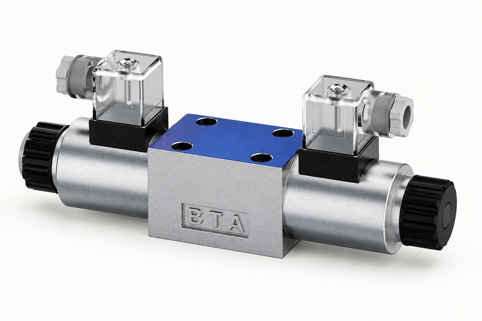
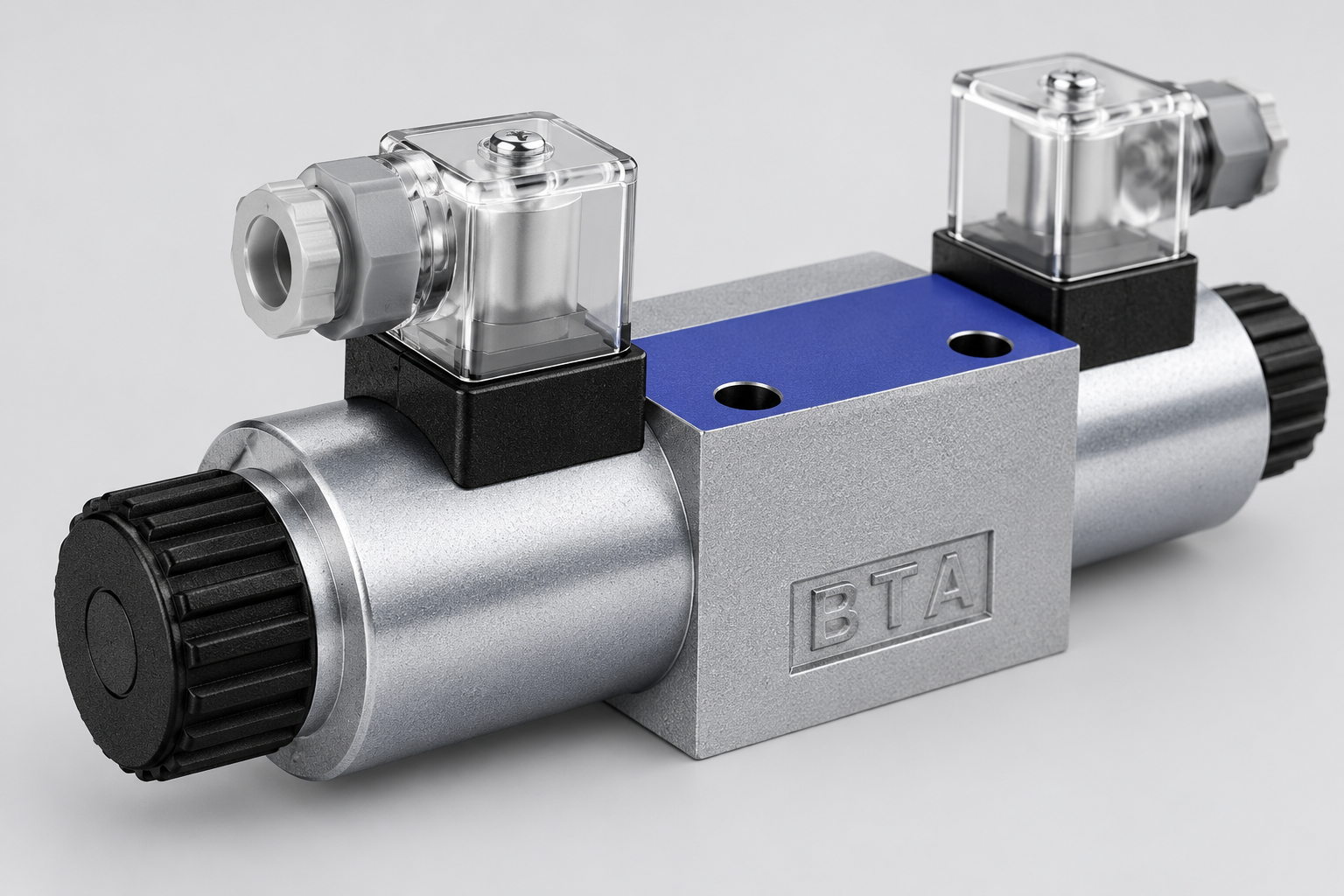
Prance's 4WE directional valve family is a relevant starting point for an on-off directional-control enquiry. Its exterior illustration identifies the valve housing and solenoid arrangement. It does not verify that every AC and DC option is available or establish a coil interchange. Request written confirmation for the actual valve, coil and connector combination being ordered.
Record acceptance results
Before returning a machine to service, verify the restored wiring against the schematic and the ordered codes. Confirm that the electrical supply and control output meet the component requirements. Check operation through the intended duty cycle under approved conditions, observing both shifting and release behaviour.
Record the measured supply, current where applicable, temperature conditions and actuation sequence. An initial successful shift is not the same as proving sustained duty. A coil that overheats later may have an incorrect rating, inadequate supply configuration or an obstructed magnetic assembly. Investigate the complete system before repeatedly replacing windings.
Keep the original and replacement codes in the maintenance record, including any connector changes. This prevents a later technician from treating the new coil as an interchangeable generic spare. A precise purchasing record reduces both electrical uncertainty and avoidable valve downtime.
Preguntas frecuentes
Can a 24 V AC coil replace a 24 V DC coil?
Not merely because the nominal voltage matches. Their winding and magnetic designs, current demand and supply requirements can differ. Use the valve manufacturer's approved coil and connector combination.
Does a plain DC coil have the same inrush as an AC solenoid?
No. A simple DC inductive winding has a rising current response. A conventional AC solenoid can have distinct pull-in and holding currents as the magnetic gap changes. Electronic boost circuits introduce a separate driver-specific case.
Can resistance alone determine the correct replacement?
No. Resistance is only one check. Confirm AC or DC supply, frequency where relevant, duty, magnetic assembly, connector electronics and approved mechanical fit. An ohmmeter does not measure the complete AC operating impedance.
Why does the valve operate with one connector but not another?
The connectors may contain different rectification, suppression, indicators or wiring. Establish their exact codes and diagrams. Inspecting only the cable voltage can miss a critical circuit inside the connector.
Should I increase voltage if the valve does not shift?
Do not exceed the documented supply requirements. Investigate voltage loss, control output, coil compatibility and mechanical obstruction using an approved procedure. Excess voltage can create overheating while leaving the original hydraulic fault unresolved.
Related products and engineering guides
Válvula direccional 4WE, related hydraulic product range, Hydraulic Solenoid Coil Resistance Test: Ohms and Temperature, Hydraulic Solenoid Valve Voltage Drop: Testing 12V and 24V Coils, ¿Cómo debe un equipo de control elegir solenoides simples o dobles?. Provide the circuit, fluid, duty and exact ordered configuration when requesting component-specific data.
University lesson: 5.1 – Directional Control Valves
This NPTEL university lecture explains the component principles underlying this guide; the lecture is background education rather than a configuration-specific test procedure.

Technical references
- NPTEL: directional control valve principles
- OpenStax: resistance and inductance in coil circuits
- NIOSH: hazardous-energy isolation
Sources support the stated principles and method scope. Illustrative inputs and another manufacturer’s documents do not establish Prance component ratings, warranties or brand affiliation.