Wenzhou Prance Hydraulic Equipment Co., Ltd.

Dimensionamiento de respiraderos de depósitos hidráulicos: flujo de aire, filtración y respiración del tanque
Hydraulic reservoir breather filter sizing starts with the fastest net change in the reservoir’s liquid volume and the pressure drop allowed through the complete air path. Pump nameplate flow alone is not a reliable sizing value because much of that oil may return to the same tank at the same time. Select a breather with documented inward and outward airflow performance, suitable particle and moisture control, and acceptable resistance as it loads. This guide concerns vented hydraulic reservoirs. Sealed or pressurized tanks require their own approved pressure-management design and cannot be converted by fitting an ordinary vented cap.
Why a reservoir needs an air path
When the liquid level falls in a vented tank, the air space expands and outside air must enter. When the level rises, air must leave. A breather filters that exchange while allowing the tank to remain within its designed pressure range. Dust and moisture entering through the air path can affect fluid condition, so a plain opening is not an equivalent replacement for a specified filter.
The breather is not the same component as an oil return filter or suction strainer. Its medium handles air exchange, and its performance must be assessed using air-service information. A liquid filter’s nominal flow rating cannot simply be reassigned to a breather. Similarly, a small particle rating does not reveal how much resistance the assembled breather creates at the required airflow.
NASA’s hydraulic ground-safety guidance identifies filtration and desiccant protection at the opening of unpressurized reservoirs as contamination-control measures. That document addresses its own safety context. It supports attention to the air-entry route, but it does not prescribe a universal industrial breather size or make every desiccant assembly suitable for every installation.
Calculate net tank exchange before choosing a size
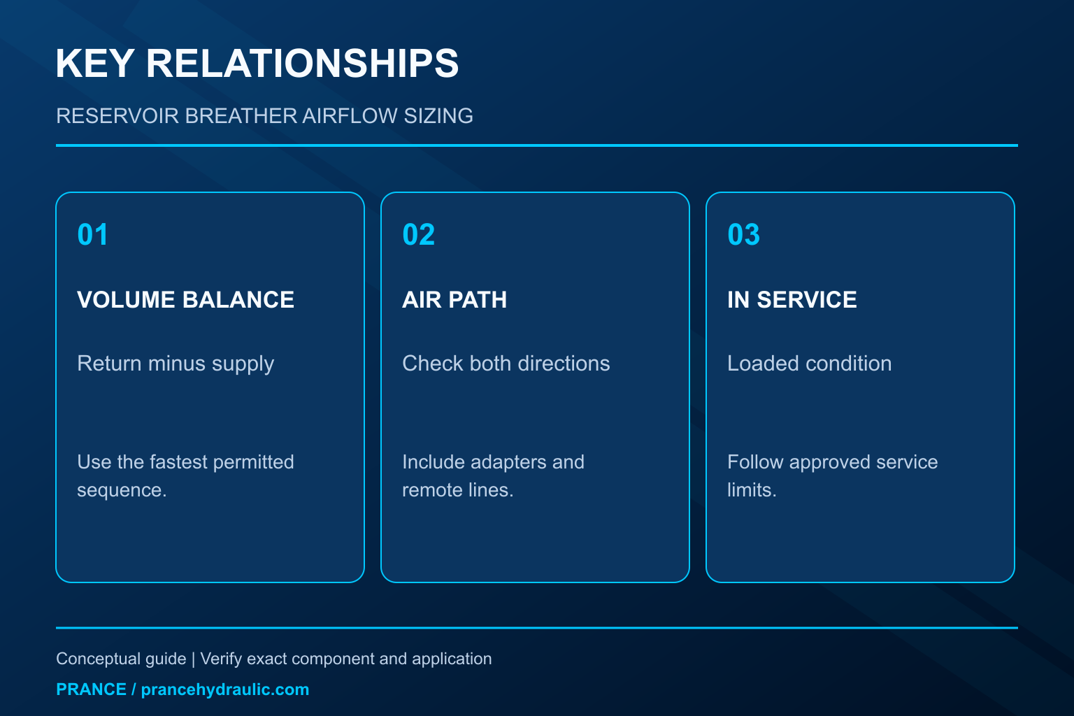
For a simple volume balance, define net liquid inflow as all return flows entering the tank minus all flows leaving it. The required air exchange follows that net rate in the opposite direction when tank pressure remains near ambient. Use consistent volume-per-time units and identify whether a supplier’s air rating refers to actual or standardized conditions.
A pump circulating oil through a motor and back to the same reservoir may produce a much smaller net level change than its gross delivery suggests. Conversely, a cylinder circuit, a filling operation or a gravity return can generate an exchange peak that differs from normal pump flow. Map the operating sequence rather than choosing one convenient rating from the power-unit label.
Include simultaneous functions where the machine permits them. Two motions that can occur together must be combined using their signed effects on tank volume. If the control system prevents that combination, document the restriction. Do not sum every actuator’s maximum flow as though all functions always occurred simultaneously, and do not ignore a permitted combination because it is uncommon.
A single-rod cylinder explains the difference
During extension, the cap end takes more liquid than the rod end returns. With both paths connected to the same reservoir through the circuit, the tank loses the difference. For an ideal single-rod cylinder, that difference equals rod cross-sectional area multiplied by extension velocity. During retraction, the direction of the net exchange reverses. Leakage, other functions and circuit routing must be included where relevant.
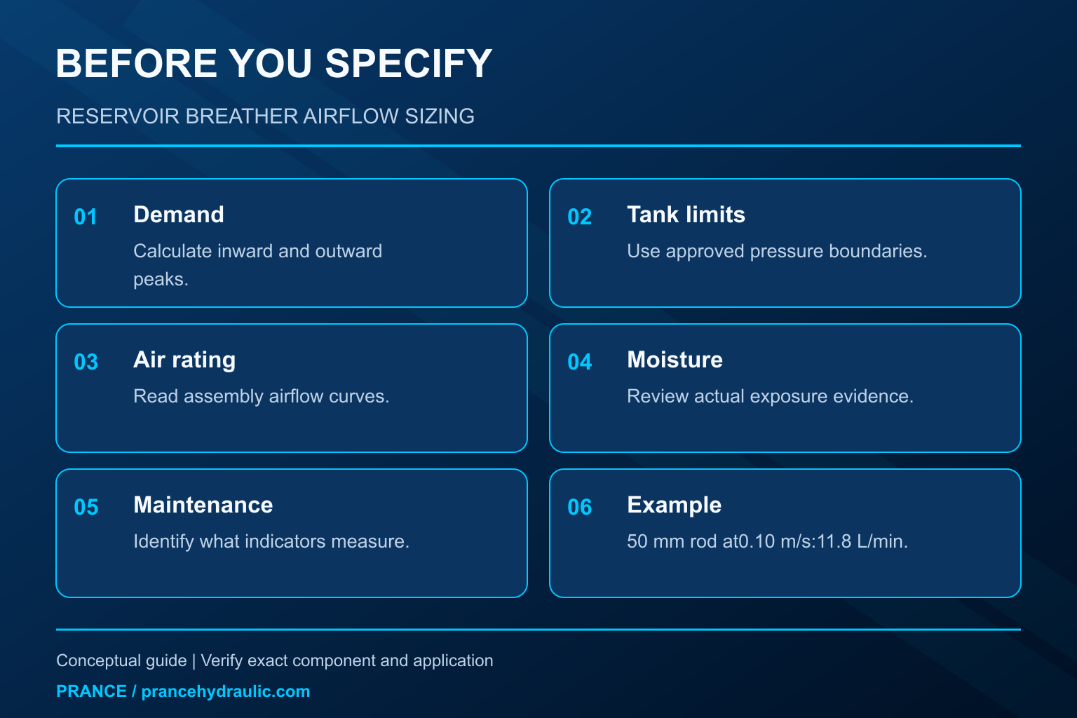
For an illustrative calculation, assume a rod diameter of 50 mm and a constant extension speed of 0.10 m/s. Rod area is pi multiplied by 0.05 squared, divided by four, or approximately 0.001963 square metres. Multiplying by velocity gives 0.0001963 cubic metres per second. Multiplying by 60,000 converts this to approximately 11.8 litres per minute of net tank liquid loss and inward air demand under the simplified assumptions.
These are assumed dimensions and operating conditions, not Prance product data. The calculation does not select a breather by itself. A selected assembly must pass the required airflow within the permitted tank pressure difference, including its connections and service condition. Additional motion, filling, thermal changes or stored-fluid return may establish a higher demand.
Check both airflow directions
A breather can have different restrictions for incoming and outgoing air. Check valves, seals, splash barriers and the media arrangement may produce different opening or pressure-drop behavior. Read the complete assembly curve or data rather than assuming that an inlet rating also proves the outlet condition.
The permissible tank vacuum and positive pressure depend on the reservoir, seals and connected components. Do not invent an allowable value from a general article. A lightly constructed tank may be vulnerable to deformation, while an inlet-sensitive pump can be affected by a pressure deficit above the oil. Use the most restrictive applicable condition when reviewing the complete system.
Installation resistance also matters. A narrow adapter, long remote hose, obstructed protective cover or restrictive connector can undo the benefit of a larger filter element. Obtain or assess pressure loss for the assembled route. Where the service environment requires remote mounting, include that route in the selection instead of evaluating the breather in isolation.
Separate airflow, filtration and moisture decisions
| Selection question | Evidencia a solicitar | Mistake to avoid |
|---|---|---|
| Can the tank breathe during the fastest permitted sequence? | Inward and outward airflow versus pressure difference for the assembly | Using gross pump flow without a tank-volume balance |
| Is particle ingress controlled? | Air-filtration performance and its stated test basis | Assuming an oil-filter rating is an air-filter rating |
| Is moisture control needed? | Environmental exposure, moisture history and desiccant service information | Treating every water problem as a breather problem |
| Will resistance remain acceptable in service? | Loading limits, indicators and replacement criteria | Selecting only by the clean element’s performance |
| Does the installation preserve the rating? | Port, adapter, mounting and remote-line details | Ignoring a restrictive connection below the filter |
This table is a selection framework rather than a model specification. It combines the tank-volume balance with contamination-control principles. Final acceptance requires the selected breather’s own documentation and the reservoir’s approved pressure limits. No particle rating, safety factor or replacement interval is universal across the applications covered here.
Clean performance is only the starting condition
A new, dry, clean breather normally represents a different condition from a loaded or moisture-affected assembly. Dust accumulation, oil mist, water exposure and contamination at the mounting can alter the air path. Review the manufacturer’s service limits and any indicator’s actual meaning. A moisture indicator is not automatically a measurement of particle loading or airflow resistance.
Choose a maintenance approach that fits the real environment. Outdoor equipment exposed to washdown has different protection needs from an enclosed indoor power unit. A breather close to dust generation or hot oil mist may need a different location or protective arrangement. Any change must preserve the necessary airflow and prevent unfiltered entry through alternative openings.
Avoid extending service solely because the outside of the cap looks clean. Equally, do not replace a component on an arbitrary short calendar interval without considering its specified service criteria. Use documented inspection and replacement rules, with actual operating evidence where the equipment permits monitoring.
Recognize a restricted air path without an unsafe test
A restricted breather may contribute to tank pressure changes during level movement. Symptoms can appear only during a fast function or after a period of contamination exposure. Pump noise, a changing inlet condition or tank distortion may accompany the problem, but none of those observations uniquely proves that the breather is responsible.
Where approved, suitable pressure measurements can compare the tank air space with ambient pressure during the relevant sequence. Correlate the result with liquid level, motion and operating temperature. Measurements should follow the equipment’s procedure and use an authorized connection; do not drill or open an operating reservoir to obtain a reading.
Do not remove the cap while the machine is running as a casual diagnostic experiment. That can expose the system to contamination, release unexpected pressure or hot fluid, and defeat the intended protection. Stop, isolate and follow the documented inspection method. A deformed tank or an exceeded pressure boundary requires investigation before further operation.
Distinguish breather restriction from suction losses
The pressure available at a pump inlet depends on the tank air-space pressure, fluid elevation and losses through the supply path. A clogged breather affects one part of that relationship. A restrictive inlet hose, an unsuitable fitting, a blocked strainer or cold viscous oil affects another. Correcting one restriction does not prove that all remaining inlet conditions are acceptable.
The Prance A10VO 31 series page provides a relevant pump category for this inlet-condition discussion. It does not establish the breather specification for an arbitrary reservoir. Check the exact pump configuration’s permitted inlet conditions and the complete installation before concluding that a chosen air filter protects the pump adequately.
If symptoms remain after replacing a confirmed defective breather with the correct assembly, revisit the inlet route and fluid condition. Avoid increasing drive speed or changing a pressure setting to mask a supply deficit. The appropriate response is to identify the pressure losses and correct the documented cause.
Include filling, draining and unusual operating states
Normal production movement may not create the largest air-exchange demand. Fast oil filling displaces tank air outward, while draining can require substantial inward flow. An elevated actuator returning oil under gravity or a separate circuit releasing stored fluid can change the tank level differently from routine powered movement. Include permitted maintenance and recovery sequences in the review.
Thermal expansion and cooling also change the relationship between liquid volume, air space and pressure. They may be slower than an actuator transient, but they still matter to a tank that spends long periods idle or sees large ambient changes. Do not apply the simple cylinder example to a sealed tank or assume that a breather automatically provides an approved pressure-relief function.
Identify every opening that can bypass filtration. A sound breather cannot prevent dust entering through a missing filler seal or an unprotected opening. Investigating repeated contamination requires reviewing oil handling, seals and other possible sources alongside the air path, rather than repeatedly fitting a finer breather without finding the ingress route.
Give the supplier a usable selection request
Send the calculated maximum inward and outward air demand, the sequence producing each peak, the reservoir’s pressure limits and the complete connection arrangement. Describe temperature, humidity, dust, washdown and oil-mist exposure. State whether moisture control is required and provide any existing contamination or pressure measurements.
Request the assembled airflow curve, filtration basis, connection dimensions, mounting restrictions and service criteria. Confirm whether any indicator measures moisture, restriction or another condition. The required outcome is an identified assembly with a defensible operating boundary and a practical maintenance method.
After installation, verify normal level-changing sequences according to the machine’s commissioning procedure. Record the exact assembly identity and preserve the sizing assumptions. If the machine gains another actuator or a faster cycle later, review the air-demand calculation again instead of assuming that the original selection remains valid.
Preguntas frecuentes
¿Debe coincidir el caudal nominal de aire del respiradero con el caudal de la bomba?
No automáticamente. Comience con la tasa neta de cambio de volumen de líquido en el depósito. La circulación bruta puede volver en gran medida al tanque, mientras que una operación de cilindro o mantenimiento puede crear un pico de intercambio diferente.
Does a larger tank require a proportionally larger breather?
La capacidad del depósito por sí sola no determina el flujo de aire máximo. La tasa de cambio del volumen de operación, los límites de presión, las conexiones y el entorno de servicio son entradas de tamaño más directas.
Is a desiccant color change a clogging indication?
No necesariamente. Siga la interpretación del fabricante de su indicador. La condición de humedad y la restricción del flujo de aire son propiedades diferentes y pueden requerir diferentes revisiones de servicio.
Can a breather cure every pump inlet problem?
No. Supply-line losses, fluid viscosity, elevation, fluid level and other restrictions also affect inlet conditions. Verify the whole inlet path against the exact pump’s documentation.
Can I use an ordinary breather on a pressurized tank?
Only if the tank’s approved design specifically permits that assembly and pressure-management arrangement. This vented-reservoir sizing method does not authorize conversion of a sealed or pressurized reservoir.
Recursos de producto y ingeniería relacionados
The Variable Displacement Pump OEM A10VO 31 Series is the relevant pump category for this inlet-supply discussion, not a breather specification. The illustrations explain concepts and do not depict the product internals or establish operating limits. Confirm the complete code and approved documentation. Related resources: Bomba de desplazamiento variable OEM serie A10VO 31, gama de bombas hidráulicas, Condiciones de la entrada de la bomba hidráulica: una lista de verificación para el comprador antes de realizar el pedido, Dimensionamiento de la línea de succión de la bomba hidráulica: velocidad, vacío y diámetro de la manguera.
Fuentes y límites de esta guía
University and government sources establish general engineering and safety principles. Exact product ratings, settings and installation limits require the approved model-specific documentation. NASA guidance cited here is scope-specific and is not a universal industrial breather specification.
- NPTEL: Fundamentos de la hidráulica y la neumática industriales
- NIOSH: prevención de lesiones por energía peligrosa
- NASA-STD-8719.24 annex,12.5.1.10.12: unpressurized reservoir breather contamination protection
Lección universitaria: principios de funcionamiento
NPTEL IIT Kharagpur presents Lecture 39 : Hoses, Filters and Coolers. The lesson supports the filtration and hydraulic supply principles; the lesson is not a model-specific breather selection approval used in this discussion; it is not a model-specific performance or installation approval.