Wenzhou Prance Hydraulic Equipment Co., Ltd.

Orbit Motor Internal Leakage: Wear Points and Diagnostic Tests
Orbit motor internal leakage is flow passing through internal clearances instead of contributing directly to useful shaft motion. Some internal flow is part of the design and supports lubrication or other functions; excessive leakage under defined conditions can reduce speed and efficiency and increase heating. Evaluate the selected motor at known pressure difference, speed, temperature and fluid condition. A case-drain reading alone does not measure every leakage path in every orbital motor.
This guide helps maintenance teams and buyers distinguish a meaningful leakage test from an isolated flow observation. It does not provide a universal acceptable drain rate or claim that every slow orbital motor needs replacement.

Identify the orbital motor configuration
Orbital motors use an internal gear arrangement and a distributor that directs oil to the expanding and contracting chambers. Different designs can use different valve arrangements, seals, drain paths and bearing options. Record the full code and actual circuit before selecting a test procedure.
Confirm whether the motor has an external case drain and how leakage is routed internally. A drain-free configuration is not automatically free of internal leakage. Conversely, a visible drain flow does not necessarily describe all flow that bypasses useful displacement. The connection and measurement definitions must match the selected motor.
Separate internal leakage from an external leak
External leakage is oil escaping from a seal, fitting or joint to the environment. Internal leakage can circulate between pressure regions or reach the housing through designed clearances. A motor can lose performance internally without visible oil on the outside, while an external fitting leak may not indicate a worn rotating group.
Document each observation separately. Clean and inspect external surfaces using a safe procedure, then evaluate performance under defined conditions. Do not label oil near the shaft as proof of excessive internal leakage without establishing the leak origin and housing pressure. Several faults can coexist and require different corrective actions.
Interpret speed loss using flow and displacement
For a fixed-displacement motor, theoretical speed is related to inlet flow divided by displacement in consistent units. In practical metric form, theoretical rpm is approximately 1000 times flow in L/min divided by displacement in cubic centimeters per revolution. Actual speed is lower when flow is lost from useful displacement under the relevant definition.
For an illustrative point, 20 L/min supplied to a 100 cubic-centimeter-per-revolution motor corresponds to 200 rpm theoretically. If measured speed is 180 rpm under a defined test, the ratio is 0.90. That example illustrates a volumetric-efficiency calculation; it is not an acceptance limit or proof that any selected product is worn.
Measure actual inlet flow rather than assuming pump delivery
A commanded pump flow or a nameplate displacement calculation may differ from the flow reaching the motor. Valve bypasses, relief flow, other actuators and pump losses can reduce available inlet flow. If the machine slows, verify flow at the relevant location before attributing the entire speed difference to motor leakage.
Document the flow meter's range, pressure-loss contribution and installation location. A restrictive meter can change the motor condition being tested. Keep the circuit within the approved limits and use suitable rated connections. An instrument inserted without considering the circuit can turn a diagnostic test into a new source of pressure or filling problems.
Control temperature and pressure difference
Leakage and friction change with oil viscosity and operating condition. A warm motor test cannot be compared directly with a cold reading at another pressure. Record fluid designation, oil temperature, both work-port pressures and speed together. Stabilize the test according to the approved method and keep the operating point repeatable.
Outlet pressure matters because the driving differential is inlet minus outlet pressure. Case pressure is separate and can affect seal and housing conditions. Do not use a single pump gauge as a complete description of the motor. The pressure measurements need defined locations and consistent references.
Understand what the drain meter includes
An external drain can carry housing leakage and, in some assemblies, intentional flushing flow. Before diagnosing wear, identify every contributor. A configuration with integrated flushing can show more case flow than a leakage-only arrangement even when both are serviceable at their respective duties.
Some internal leakage may return through a work port rather than the external drain. Therefore, a low drain reading does not prove excellent volumetric performance. Compare the drain test with inlet flow and shaft speed using the selected motor's method. Do not change drain routing or block a line to create a convenient isolated measurement.
Use a leakage investigation table
| Observación | Alternative explanation to check | Useful measurement |
|---|---|---|
| Lower speed at the same command | Less flow reaching the motor | Actual inlet flow and shaft speed |
| Higher drain flow when warm | Changed viscosity, pressure or flushing contribution | Temperature, differential pressure and flow definition |
| Low speed with normal drain reading | Internal work-port leakage or another circuit loss | Inlet flow, outlet condition and approved efficiency test |
| Higher temperature | Hydraulic losses, brake drag or external mechanical load | Pressures, torque demand and brake-release signal |
| Uneven low-speed rotation | Distributor behavior, load control or mechanical stick-slip | Speed pattern, pressure trace and installed duty |
| Performance change after service | Wrong assembly, cartridge or connection | Part identity and before-and-after configuration |
The table prevents a single reading from becoming an automatic wear diagnosis. Establish the operating condition and competing explanations first.
Review distributor and rotating-group condition
Wear or damage in the gear set and distributor can affect performance, but dismantling requires the correct procedure and inspection limits. Preserve orientation and matched components when a qualified repair assessment is undertaken. A photograph of a polished surface does not establish whether it exceeds a service limit.
If a repaired motor performs poorly, compare the assembly code, valve arrangement and parts used. An incorrect internal timing or matched-part combination can produce symptoms different from ordinary wear. Ask the repair provider for measured findings and the basis for the repair decision rather than accepting a general statement that the motor looked worn.
Exclude the brake and driven load
A dragging brake or overloaded transmission can slow the shaft and raise pressure and temperature. Check release pressure, coupling alignment and external load before assuming that internal leakage is the only issue. A motor with acceptable leakage can still fail to move a machine when required torque exceeds its available starting performance.
Where an approved controlled test separates the motor from the driven load, document the changed conditions. Unloaded behavior is useful evidence but not a substitute for the loaded operating point. Keep speed, flow and pressure relationships clear so a lower load is not mistaken for a repaired internal condition.
Compare results with configuration-specific criteria
Use the selected motor's technical data or agreed acceptance method. Distinguish production limits, repair limits and performance curves. A curve showing typical efficiency may not be a guaranteed acceptance threshold for every supplied unit. Ask the supplier which criteria apply to the serial-specific test and actual duty.
Repeat measurements when a result is close to a limit and review instrument uncertainty. Do not accept or reject a motor based on excessive displayed precision. Record raw readings, stabilized conditions and any corrections so the comparison can be reproduced and evaluated by another reviewer.
Decide between circuit correction and motor repair
If inlet flow, valve behavior, drain pressure or brake release explains the issue, correct that verified condition and repeat the test. Replacing the motor without addressing the circuit can leave performance unchanged. If controlled evidence shows internal performance outside the applicable criteria, obtain a repair or replacement assessment.
For repair, inspect the relevant internal components, fits, seals and passages under the approved process. Do not substitute a general seal kit for an assessment of rotating-group or distributor wear. For replacement, verify the full interface and duty requirements rather than selecting the same nominal displacement alone.
Keep a useful leakage trend
Trend readings only under comparable conditions. Use the same relevant pressure, speed, oil temperature and measurement arrangement. A higher flow measured during a different duty is not automatically deterioration. Keep machine changes, oil changes and valve replacements with the data so a trend can be interpreted in context.
Define maintenance triggers with the supplier or machine procedure. The objective is to identify a meaningful change before severe failure while avoiding unnecessary replacement. A baseline taken after verified commissioning is particularly useful because its operating conditions and configuration are known.
Information to send for supplier review
Provide the motor code, circuit schematic, fluid and temperature, measured inlet flow, speed, both working pressures and case pressure. State whether drain flow includes flushing and describe the test equipment and locations. Include the symptoms, duty and any recent maintenance or control change.
Ask which leakage and efficiency criteria apply and whether additional measurements are needed. Request a distinction between confirmed performance loss and proposed causes. A quotation for another motor should not replace the diagnosis or the evidence needed to prevent the same issue after installation.

Preguntas frecuentes
Is all internal leakage a defect?
No. Designed clearances and lubrication involve internal flow. Evaluate performance against the selected motor's accepted conditions rather than expecting zero leakage.
Does case-drain flow measure total internal leakage?
Not for every design. Some leakage follows internal working-line paths, and drain flow can include flushing. Confirm the measurement definition for the exact configuration.
Why does leakage increase when oil becomes warmer?
Viscosity and clearances influence flow through internal paths. Compare readings at the same pressure, speed and temperature before diagnosing deterioration.
Can a slow motor have another cause?
Yes. Low inlet flow, valve losses, brake drag and excessive mechanical load can reduce speed. Measure actual flow and the complete operating state.
What makes a leakage trend meaningful?
Comparable operating points, verified configuration and repeatable instruments. Keep temperature, pressure, speed and maintenance changes with each reading.
Recursos de producto y ingeniería relacionados
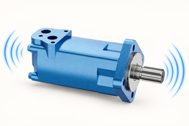
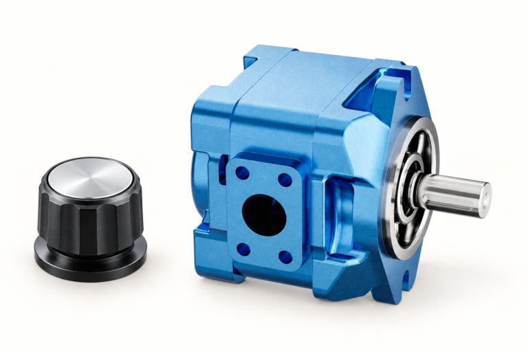
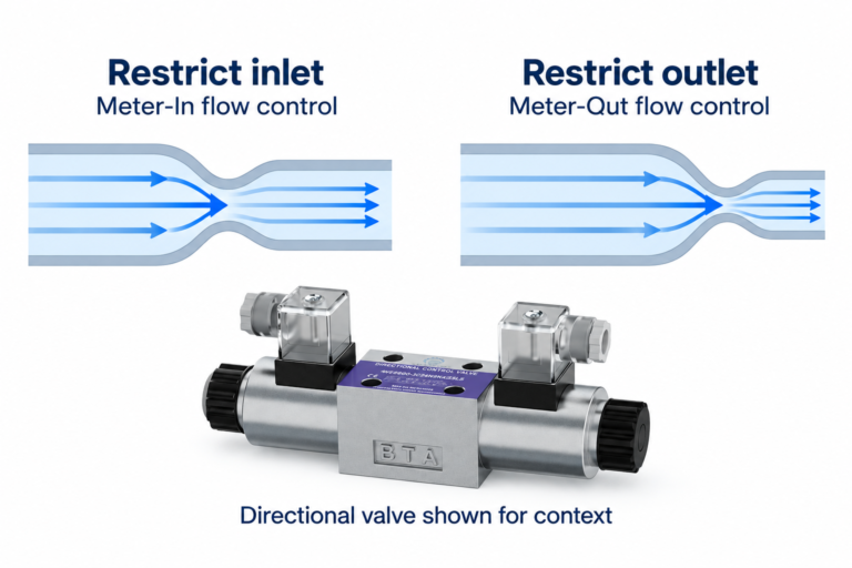
Para una consulta sobre un componente, consulte Motor orbital gerotor hidráulico BMS y proporcionar la especificación completa y las condiciones de instalación. Guías relacionadas: Gamma de motores de pistón, Rango de motor orbital, Revisiones de presión en el alojamiento del motor, Medición del flujo de drenaje del motor, Calculo de la eficiencia del motor, Hydraulic Motor Factory Test Report: Torque, Speed, and Leakage, Orbit Motor Valve Timing: Gerotor Commutation Explained. Las fotografías de los productos ilustran las configuraciones del catálogo; no indican la presión, la velocidad ni la capacidad de carga del eje para un pedido no confirmado.
Conferencia universitaria: fundamentos del motor hidráulico
NPTEL-NOC IITM presenta una lección sobre motores hidráulicos del IIT de Madrás. La conferencia explica la distinción entre la entrada hidráulica y la salida del eje utilizada en esta guía. Las limitaciones de instalación y funcionamiento específicas de los componentes aún requieren la documentación del motor seleccionado.
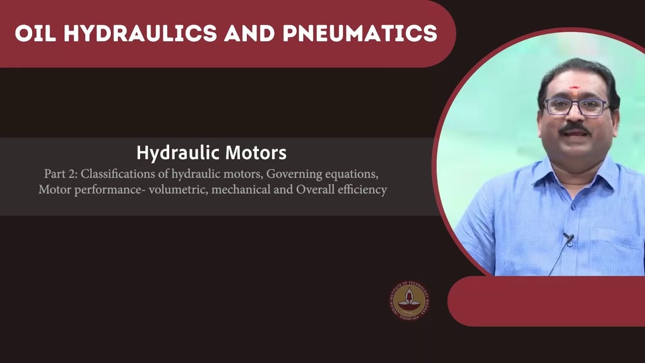
Obre la conferencia sobre los motores hidráulicos de NPTEL.
Referencias técnicas y de seguridad
- NPTEL: Fundamentos de la hidráulica y la neumática industriales
- NIOSH: prevención de lesiones por energía peligrosa
- Referencias técnicas: principios de funcionamiento de los motores orbitales y instalación
Estas referencias proporcionan contexto educativo y técnico. Las calificaciones específicas del modelo de un fabricante de referencia no son especificaciones para un producto Prance y no implican afiliación ni autorización de la marca.