Wenzhou Prance Hydraulic Equipment Co., Ltd.

Variable Vane Pump Pressure Compensation: Cam-Ring Control Explained
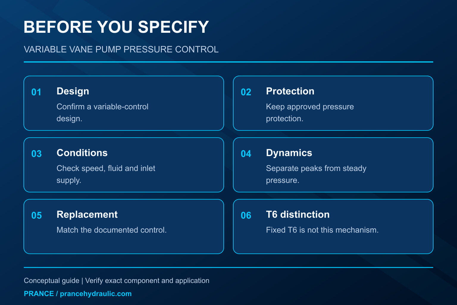
Variable vane pump pressure compensation reduces delivered flow by moving the cam ring toward the rotor center as outlet pressure approaches the control setting. Less eccentricity means less displacement per revolution. When demand falls, the control reduces displacement instead of sending the pump’s full delivery across a relief valve. This explanation applies to a vane pump specifically designed with a movable ring and a pressure-control mechanism. A fixed-displacement vane pump does not acquire that function because its installation includes a relief valve. Identify the exact pump design before comparing pressure settings, energy consumption, or replacement options.
What the cam ring actually changes
The rotor turns inside the cam ring, and sliding vanes divide the surrounding space into chambers. In a simplified unbalanced vane-pump arrangement, the rotor axis and ring center are offset. Chamber volume increases on the inlet side and decreases on the outlet side. That changing volume transfers fluid through the pump. This is a displacement process; the pump does not independently command both flow and pressure.
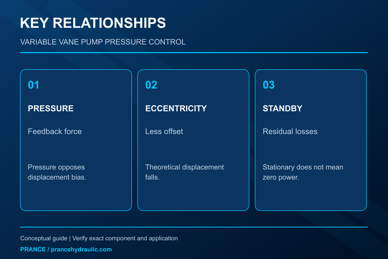
A variable design changes that offset. Moving the ring closer to the rotor center reduces the difference between the largest and smallest chamber volumes. At a given shaft speed, theoretical delivery decreases. Moving it farther away increases displacement within the permitted travel. The internal arrangement, control pistons, springs, bearings and port geometry vary by manufacturer. An educational mechanism should never be treated as a machining or assembly drawing for an unidentified product.
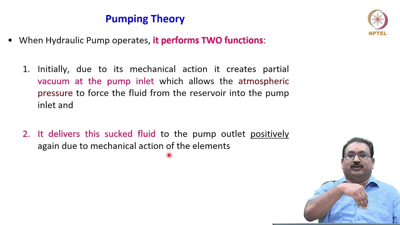
The IIT Madras NPTEL hydraulic-pumps lecture explains this relationship between eccentricity and delivery. Its simplified pressure-compensated example shows outlet pressure opposing a spring-supported ring. That establishes the operating principle. It does not establish the pressure rating, adjustment direction, permissible speed, or service procedure of a commercial pump.
How pressure feedback moves the ring
Below the control region, the mechanism permits relatively high displacement because the load is accepting flow. As resistance increases, outlet pressure produces a control force that opposes the displacement bias. The ring moves toward reduced eccentricity, so delivery falls. If an actuator stops and normal flow demand disappears, the pump can approach a low-displacement standby condition while maintaining pressure against system leakage.
This feedback is not instantaneous. The ring has mass, the fluid is compressible, and control passages introduce restrictions and delays. A sudden valve closure can produce a transient peak before the mechanism settles. A stable pressure reading after the event therefore does not prove that transient pressure remained acceptable. Transducer placement, sampling rate and the machine’s protection devices matter when investigating an abrupt stop.
Nor does the ring necessarily move to a mathematically perfect zero-delivery state. Leakage, lubrication and the control’s operating requirements influence actual standby behavior. Avoid assuming that a stopped actuator means zero pump flow, zero shaft power or zero heat. The permitted standby condition must come from the exact pump documentation and the circuit design.
Pressure setting and displacement limit serve different purposes
A pressure compensator responds to pressure feedback. A displacement limit restricts how much volume the pump can deliver per revolution. Where both are available, they affect different parts of operation: limiting maximum displacement can limit available actuator speed, while pressure compensation reduces displacement when the load pressure reaches the control region. Neither adjustment substitutes for checking the drive motor and system protection.
Some assemblies also offer remote controls, special unloading arrangements or other options. Those features cannot be inferred from the words “variable vane pump.” Read the complete ordering code and its matching schematic. Two pumps with similar housings can have different control behavior, connections, or permitted operating conditions. A photograph is useful for identity and mounting questions, but it cannot establish the internal feedback arrangement.
Do not turn an unknown screw to determine its purpose. An incorrect change may remove a protective limit or produce unexpected movement. Identify the manufacturer procedure, isolate the machine, release stored energy and have qualified personnel perform any authorized adjustment using suitable instruments.
Compare three common circuit arrangements
| Arreglo | What happens when demand stops | What must be verified |
|---|---|---|
| Fixed-displacement pump with relief protection | Delivery continues unless speed changes or an unloading route opens; relief flow can create heat | Actual unloading route, relief duty and cooling capacity |
| Variable vane pump with pressure compensation | Displacement reduces as pressure feedback moves the ring | Exact compensator, standby limits and stability |
| Variable pump with an additional unloading function | The circuit may reduce standby pressure through a separate approved function | Control sequence, restart response and fail-safe behavior |
This is a qualitative operating comparison, not a product parameter table. The university mechanism supports the second row’s principle. The other rows describe circuit behavior that must be confirmed from a complete hydraulic schematic. An efficient operating result depends on the load cycle, losses and control arrangement; the pump label alone does not establish energy savings.
Why a relief valve remains part of the review
Pressure compensation manages normal delivery as pressure changes. A relief valve or another suitable protective arrangement addresses pressure limitation according to the circuit’s design. Do not remove a protection device because a simplified diagram suggests that the pump can reduce its own delivery. Trapped fluid, external loads, switching events and separate branches can create pressure conditions beyond the pump control’s immediate influence.
The relationship between normal compensator operation and protective-valve opening must follow the machine and component documentation. There is no universal pressure separation that can safely be applied to every assembly. Overlapping control regions can cause undesirable interaction; excessive separation can leave components inadequately protected. Both problems require a system-level review.
An elevated standby temperature also does not identify which valve is responsible. Check whether the pump is remaining at unnecessary displacement, whether an unloading function operates, and whether another circuit is continuously accepting flow. Follow an approved test sequence rather than disabling valves one at a time to see what changes.
Reading a pressure-and-flow test
A useful test establishes shaft speed, fluid condition, inlet conditions, outlet pressure and delivered flow under specified operating states. Compare a working-flow condition with an approved standby condition. The expected trend is reduced delivery as the pressure control acts, but the acceptable slope, residual flow and pressure stability belong to the exact pump specification.
Instrument readings need a common time reference when a transient is involved. A pressure peak and a later low-flow reading do not describe the same instant. Separate steady operation from switching response. A mechanical gauge may be adequate for a slowly changing condition yet fail to capture a brief event. Select equipment and procedures appropriate to the suspected fault.
If available delivery falls at all pressures, first verify shaft speed, drive condition, fluid temperature and inlet supply. If flow is acceptable at low pressure but collapses too early as load rises, the control, internal leakage or operating conditions may warrant investigation. These observations narrow the problem; they do not authorize dismantling a pressurized pump or changing a setting without documentation.
Distinguish control trouble from inlet trouble
Air entry, an excessive inlet restriction and unsuitable cold-fluid viscosity can impair pumping before the pressure compensator becomes the main issue. Noise alone cannot distinguish them. Note whether the symptom follows temperature, speed, fluid level or a particular machine sequence, and measure the relevant conditions within the manufacturer’s approved limits.
A restricted reservoir breather can contribute to a pressure deficit above the oil in a vented tank. A long or undersized suction path creates additional losses. Neither condition is corrected by raising the compensator setting. A higher pressure setting may increase mechanical and thermal stress while leaving the original supply problem unresolved.
Likewise, a pressure fluctuation might originate at a directional valve, a load, an accumulator or an interacting control. Review the complete circuit before condemning the ring mechanism. Stop testing if temperature, pressure, noise or motion exceeds the approved boundary, and retain the observations needed for a qualified fault review.
Match replacement behavior, not just the mounting
cURL Too many subrequests by single Worker invocation. To configure this limit, refer to https://developers.cloudflare.com/workers/wrangler/configuration/#limits.
cURL Too many subrequests by single Worker invocation. To configure this limit, refer to https://developers.cloudflare.com/workers/wrangler/configuration/#limits.
cURL Too many subrequests by single Worker invocation. To configure this limit, refer to https://developers.cloudflare.com/workers/wrangler/configuration/#limits.
cURL Too many subrequests by single Worker invocation. To configure this limit, refer to https://developers.cloudflare.com/workers/wrangler/configuration/#limits
cURL Too many subrequests by single Worker invocation. To configure this limit, refer to https://developers.cloudflare.com/workers/wrangler/configuration/#limits.
cURL Too many subrequests by single Worker invocation. To configure this limit, refer to https://developers.cloudflare.com/workers/wrangler/configuration/#limits.
cURL Too many subrequests by single Worker invocation. To configure this limit, refer to https://developers.cloudflare.com/workers/wrangler/configuration/#limits.
Preguntas frecuentes
Does moving the cam ring change pump speed?
cURL Too many subrequests by single Worker invocation. To configure this limit, refer to https://developers.cloudflare.com/workers/wrangler/configuration/#limits.
Can a fixed T6 vane pump be adjusted into a variable pump?
cURL Too many subrequests by single Worker invocation. To configure this limit, refer to https://developers.cloudflare.com/workers/wrangler/configuration/#limits.
Is standby power always zero?
No. Leakage, lubrication, control flow and mechanical losses can require power even when the actuator is stationary. Establish acceptable standby operation from the complete pump and machine documentation.
Does pressure compensation eliminate pressure spikes?
No. The mechanism takes time to respond, while switching and external loads can generate transients. Protective devices and transient assessment remain necessary according to the circuit design.
Should I increase the pressure setting when flow falls?
First establish why delivery fell and whether it occurred in the intended control region. Raising an unidentified setting can create unsafe pressure without correcting an inlet, leakage or drive problem.
Recursos de producto y ingeniería relacionados
The Fixed Displacement Vane Pump T6 is a fixed-displacement comparison product, not the variable pressure-compensated pump described here. The illustrations explain concepts and do not depict the product internals or establish operating limits. Confirm the complete code and approved documentation. Related resources: Bomba de paletas de desplazamiento fijo T6, gama de bombas hidráulicas, Bomba de paletas equilibrada frente a desequilibrada: fuerza, caudal y selección, Ajuste del compensador de presión de la bomba hidráulica: Procedimiento y riesgos.
Fuentes y límites de esta guía
University and government sources establish general engineering and safety principles. Exact product ratings, settings and installation limits require the approved model-specific documentation. NASA guidance cited here is scope-specific and is not a universal industrial breather specification.
- NPTEL: Fundamentos de la hidráulica y la neumática industriales
- NIOSH: prevención de lesiones por energía peligrosa
- IIT Madras NPTEL lecture8, section1.7.4: pressure-compensated variable vane pumps
Lección universitaria: principios de funcionamiento
NPTEL-NOC IITM presents 3.2 – Hydraulic Pumps. The lesson supports the hydraulic pump displacement and operating principles; the university pump lesson is not a model-specific commissioning approval used in this discussion; it is not a model-specific performance or installation approval.