Wenzhou Prance Hydraulic Equipment Co., Ltd

Jeu doux entre la pompe et le moteur : pourquoi le serrage d'une boulon modifie l'alignement
Hydraulic pump motor soft foot is a mounting condition in which the electric motor’s feet do not sit correctly on their support surfaces. Tightening a hold-down bolt can then distort the frame and change the shaft position. Correct the support condition before final coupling alignment; repeatedly moving the motor to compensate for bolt-induced movement treats the result rather than its cause. First establish whether the movement comes from an uneven contact surface, a compressible shim stack, an angled foot, or an external load on the assembly.
This guide concerns a stationary, isolated pump and motor drive. It does not authorize loosening bolts while the equipment operates. Follow the drive manufacturer’s isolation, support, fastening, and alignment instructions.
Why tightening a bolt can change alignment
A motor frame should rest on its intended supports without being forced into shape by the mounting bolts. When one foot sits above the base or contacts it unevenly, tightening that bolt pulls the frame toward the support. The shaft can move as the frame and bearing housings respond to the imposed distortion.
The effect can be confusing during alignment. The instrument shows an acceptable result with some bolts loose, but the result changes after final tightening. Another attempt at horizontal or vertical adjustment may produce the same cycle. Before adding more alignment corrections, determine whether the machine is returning to a stable, repeatable support condition.
Soft foot and shaft misalignment are related but different. Alignment compares the shaft axes. A soft-foot check examines how the mounted machine responds to fastening and support contact. An acceptable coupling reading at one moment does not prove that the frame is free from mounting stress, and a soft-foot correction does not by itself establish final alignment.
Recognize the main contact conditions
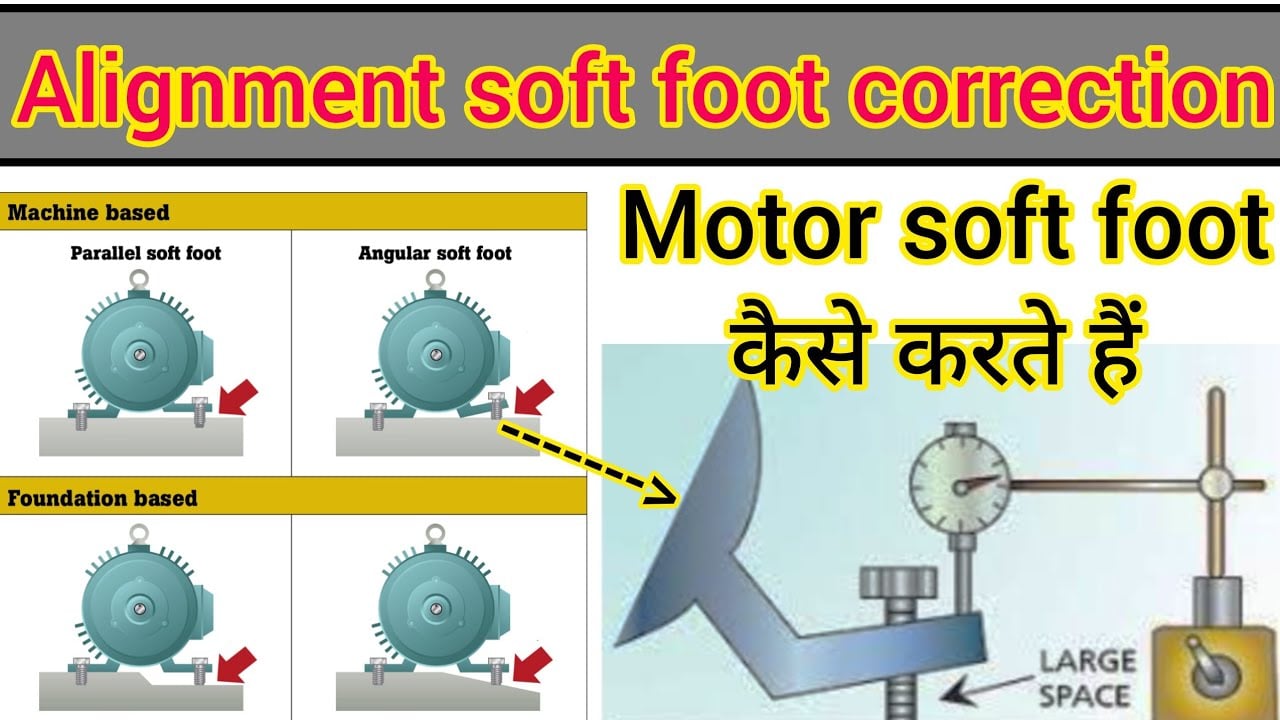
A parallel gap is the simplest case: a foot may sit approximately parallel to its base but remain above it. An appropriate full-contact shim can fill the gap, subject to the manufacturer’s permitted method. The diagnosis still requires checking why the gap exists; debris under another foot can create an apparent low corner.
An angular contact condition is different. One edge may touch while another remains clear. Adding a flat shim of arbitrary thickness can change the contact without removing the angle. Damaged feet, uneven mounting pads, or a distorted base may require an approved machining or engineered correction rather than a larger pile of shims.
A compressible support can resemble a dimensional gap. Burrs, trapped contamination, damaged shims, excessive stacked layers, or unsuitable material can settle under fastening load. If repeated tightening produces changing results, inspect the support surfaces and stack condition. Treat repeatability as evidence: a measurement that keeps drifting should not be accepted simply because one reading briefly meets a target.
Isolate the drive before measuring
Stop and isolate the motor, prevent unexpected electrical starting, and follow the hydraulic system’s stored-energy procedure. Hydraulic pressure can remain after the electric drive stops, particularly where accumulators or suspended loads are present. Verify the safe condition using the machine’s prescribed method before removing guards or working near the coupling.
Check the installation drawing to identify the reference machine and the intended adjustable machine. A flange-mounted hydraulic pump may be supported through a bell housing rather than individual pump feet. Do not apply a four-foot motor procedure to an unsupported pump housing or loosen an assembly that requires temporary support.
Inspect accessible base surfaces, bolts, washers, and shim edges before disturbing the setup. Record the initial alignment and the fully tightened condition. This preserves evidence of how the existing assembly behaves and helps distinguish an improvement from an unrelated change in the instrument mounting or measurement position.
Measure movement one foot at a time
A common stationary method places a dial indicator at the foot being examined, referenced to a stable base. With the other feet secured as specified, the selected bolt is loosened under the approved procedure and the movement is recorded. The same foot is returned to the prescribed fastening condition before proceeding to the next location.
A laser alignment instrument may provide a soft-foot routine, but follow its instructions and the machine procedure rather than assuming all displayed movement has the same cause. Indicator position, bracket stiffness, bolt sequence, and the location of the measured surface can affect what the instrument reports.
Repeat the check after a correction. Look for stable behavior over the specified sequence and compare the result with the equipment’s acceptance criterion. Published generic limits vary by machine and procedure; this article intentionally does not assign a universal permitted movement. A tolerance from a different pump installation is not automatically applicable to a hydraulic power unit.
Use the evidence to choose the correction
The table below is a qualitative diagnostic aid based on the support and alignment principles described in the EPRI maintenance reference. It is not a shim-sizing chart or a product tolerance table.
| Finding on the isolated assembly | Ce que cela peut indiquer | Étape suivante appropriée |
|---|---|---|
| A consistent gap appears across the foot | Parallel support mismatch | Verify clean surfaces and use an approved full-contact correction |
| Contact exists at one edge only | Angular mismatch or damaged pad | Check flatness and obtain an engineered correction if required |
| Results change after repeated tightening | Compressible stack, debris, or unstable support | Inspect shims, pad surfaces, fasteners, and base stiffness |
| Movement changes after external attachments are altered | Pipe, conduit, or structural loading | Review the attachment load with the equipment isolated and supported |
| Bolt reaches its limit before clamping the foot | Incorrect bolt length or mounting hardware | Verify the fastening arrangement before interpreting the reading |
| Soft-foot response is stable but shaft alignment remains wrong | Separate alignment error remains | Proceed with the specified coupling-alignment method |
Correct shims without hiding a base problem
Use shims that suit the installation, support the intended contact area, and fit without interfering with the bolt or adjacent surfaces. Clean the support pads and inspect for raised edges, corrosion, coating buildup, and damaged material. Do not insert a dirty or distorted shim into a precision adjustment and expect the final torque to make it flat.
Keep the stack within the manufacturer’s instructions. Reducing unnecessary layers can improve consistency, but there is no universal stack count that suits every machine. Never substitute soft packing, folded material, or an improvised washer arrangement for a specified full-contact support.
A correction that becomes progressively larger at several feet may indicate a broader base or installation problem. Check whether the base is supported as designed and whether tightening the base anchors distorts the mounting pads. If the structure moves, correcting only the motor-foot gaps can conceal the underlying cause. Escalate a damaged or unstable base for an appropriate mechanical assessment before final alignment.
Distinguish external strain from a foot gap
Pipes, rigid conduit, brackets, guards, and other attachments can apply force to the pump-motor assembly. A movement change associated with one of these attachments is evidence that the support condition depends on external loading. It does not justify loosening a pressurized connection or leaving a required bracket unsecured.
Where the approved installation procedure permits an isolated attachment-strain check, support the connected components and follow that procedure. Record which condition changed and compare the machine position before and after. Flexible hose is not proof of zero force: routing, stiffness, unsupported weight, and constrained bends can still affect the assembly.
Correct the source of the imposed load through approved routing, support, or structural work. Do not pull a pump into position with pipe bolts or use the motor mounting bolts to overcome a misfitting bell housing. A forced assembly can produce acceptable-looking external gaps while retaining stress in components that the alignment instrument does not directly measure.

Apply the check to the actual hydraulic pump installation
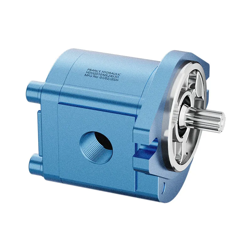
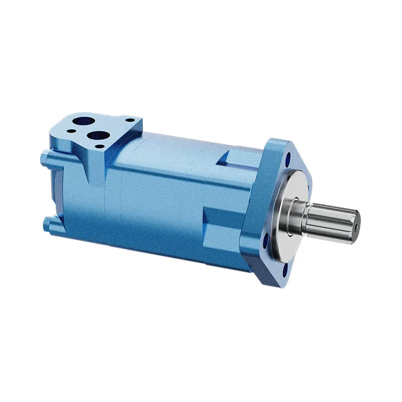
Prance’s A10VO 31-series product page provides an actual hydraulic piston-pump reference. Its original photographs show a shaft-and-flange arrangement. They do not show a completed motor base, coupling, bell housing, or a verified soft-foot fault. The photographs are included to identify the relevant pump category without inventing a customer installation.
Before assessing a power unit, obtain its actual mounting drawing. Determine whether the motor feet locate the drive on a base, whether the pump is carried by a bell housing, and whether any additional support is specified. The pump model name alone does not define that support system.
For a technical enquiry, provide the pump and motor codes, mounting arrangement, coupling type, bolt-induced movement readings, shim arrangement, and the measured alignment before and after tightening. Include photographs of the real base and feet if available. Keep measured movement separate from assumed clearances or instrument resolution so the review addresses actual evidence.

Finish with alignment and a repeatable acceptance check
Once the support condition is stable, perform the specified coupling alignment with all required final fastening steps. Use the approved torque and sequence, then remeasure. If thermal growth targets apply, use the equipment manufacturer’s values; a cold alignment target should not be invented from the motor size.
Refit guards and complete the required checks before returning the unit to operation. During the approved operating test, compare vibration, noise, temperature, and leakage with suitable baseline conditions. Improved vibration can support the correction, but it does not replace the stationary support and alignment measurements.
Retain a concise final record: support condition, correction applied, fastening condition, alignment result, and operating observation. If the reading changes again after attachments are reinstalled, investigate that change before accepting the job. The useful outcome is a drive that returns to the same acceptable position under its complete installation conditions.
Foire aux questions
Le pied mou est-il la même chose que des boulons de fixation desserrés ?
Non. Un boulon desserré relève d'un problème de fixation, tandis que le défaut de pied mou concerne la manière dont la machine entre en contact avec ses supports et réagit à ceux-ci. Ces deux problèmes peuvent coexister. Vérifiez les conditions de fixation spécifiées ainsi que le contact avec les supports, au lieu de considérer le simple serrage des boulons comme un diagnostic complet.
Une cale doit-elle être ajoutée chaque fois qu'un indicateur bouge ?
Not automatically. Movement can result from angled contact, compressible material, external strain, or unstable measurement hardware. Establish the cause and the permitted correction before selecting a shim thickness.
Une liaison flexible peut-elle compenser un pied mou ?
Un accouplement peut tolérer un déplacement limité de l’arbre dans les limites spécifiées dans sa documentation, mais il ne supprime pas la déformation du bâti du moteur et ne répare pas une surface de montage. Corrigez le support, puis vérifiez l’alignement complet de l’accouplement.
Le pied mou peut-il être vérifié pendant que le moteur fonctionne ?
This guide specifies a stationary, isolated check. Do not loosen hold-down bolts or approach exposed rotating parts during operation. Any specialist diagnostic method requires its own authorized procedure and equipment.
Quelle tolérance doit être utilisée pour l'acceptation ?
Use the installed machine’s approved support and alignment criteria together with the instrument procedure. If those are unavailable, obtain an engineering decision before accepting the assembly; do not borrow a numerical limit from an unrelated pump manual.
Ressources produits et d'ingénierie associées
Pompe à cylindrée variable série OEM A10VO 31, gamme de produits de pompes hydrauliques, Quels dossiers d'installation comptent avant l'examen d'un accouplement de pompe ?, Fréquences de vibration de la pompe hydraulique : vitesse de l'arbre, engrenage de la roue, et résonance. Confirmer le code complet du produit et les exigences d'application lors de la demande d'une revue de configuration.
Références techniques
- EPRI: Charging Pump Maintenance Guide, printed page 2-71 and Appendix D; general support principles, not limits for this drive
- EASA: Getting the Most from Your Electric Motors, alignment and soft foot
Apprentissage supplémentaire : pompes hydrauliques
Alignment soft foot correction | motor soft foot correction | how to motor soft foot correction by Engineering Guruji provides a Hindi-language soft-foot demonstration. The Hindi-language demonstration shows the contact and fastening issue discussed here. Follow the installed machine procedure for safe isolation and acceptance limits. It supplements the component fundamentals; it is not a test procedure for the complete circuit discussed above.