Wenzhou Prance Hydraulic Equipment Co., Ltd


Variable Axial Piston Pump A11VO
1.Variable displacement pump with axial piston drive swashplate design for hydrostatic drives in open circuits
2.Design primarily for use in mobile applications
3.Pump operation either self-priming,with tank charging or charging pump
4.A comprehensive range of varialble units is available for different control functions
5.Power can be adjusted from the outside , even when the machine is running
6.The through drive is suitable for attachment of gear pumps and axial piston pumps up to the same size , i.e.100% through drive
7.The Volume flow is adjustable in proportion to the dirve speed and displacement and is infinitely variable from QVmax to QvMin=0
Detailed description
The axial piston variable pump A11VO is a robust and versatile hydraulic component engineered for demanding hydrostatic drive systems, particularly those found in mobile applications. At its core, this pump utilizes a variable displacement design with an axial piston drive featuring a swashplate configuration. This fundamental design allows for precise and efficient flow control, making it highly suitable for open circuit hydrostatic drives where adaptability is key.
One of the primary advantages of this pump is its operational flexibility. It can function effectively in several modes, including self-priming operation, or it can be used in systems with tank charging or an integrated charging pump. This adaptability simplifies system design and allows the pump to be integrated into a wide variety of hydraulic circuits without extensive modification.
To accommodate diverse operational needs, the A11VO is available with a comprehensive selection of variable displacement controls. These units enable different control functions, ensuring that the pump’s output can be precisely matched to the specific requirements of the machine and its tasks. Furthermore, for enhanced on-site flexibility, the power setting of the pump can be adjusted externally, and crucially, this adjustment can be performed even while the machine is in operation, allowing for real-time optimization without downtime.
The pump’s robust construction is complemented by its thoughtful mechanical design. It features a through drive capability that is particularly noteworthy, as it is engineered to accept the attachment of additional pumps, such as gear pumps or further axial piston pumps, up to the same frame size. This allows for 100% through-drive torque, enabling a compact and efficient multiple-pump arrangement from a single drive source.
In terms of performance, the A11VO delivers highly controllable hydraulic power. The volume flow is directly proportional to both the drive speed and the displacement setting. This flow can be adjusted infinitely and steplessly across its entire operating range, from its maximum volume (QVmax) down to a negligible minimum (QVmin = 0). This precise, variable control is essential for optimizing the efficiency and responsiveness of modern mobile hydrostatic drives.
Selection and RFQ
The A11VO series is used in open-circuit hydraulic systems where variable displacement helps match pump output to load changes. Confirm displacement size, rated pressure, speed range, port layout and control option against your circuit datasheet.
Information to include in your RFQ
- Required displacement or flow at working speed
- Continuous and peak system pressure
- Control type and pilot pressure requirements
- Mounting flange, shaft, port orientation and fluid specification
Related resources
Ordering Code / Standard Program
| A11V | ○ | / | 1 | - | N | ||||||||||||
| 01 | 02 | 03 | 04 | 05 | 06 | 07 | 08 | 09 | 10 | 11 | 12 | 13 | 14 | 15 | 16 |
Axial piston unit
| 01 | Swashplate design, variable, nominal pressure 350 bar, maximum pressure 400 bar | A11V |
Charge pump(impeller)
| 02 | without charge pump (no code) | ● | ● | ● | ● | ● | ● | ● | ● | |
| with charge pump | - | - | - | - | ● | ● | ● | ● | L |
Operation
| 03 | Pump, open circuit | ○ |
Size
| 04 | ≈Displacement Yg maxin cm3 | 40 | 60 | 75 | 95 | 130 | 145 | 190 | 260 |
Control unit
| 05 | Power control | LR | ● | ● | ● | ● | ● | ● | ● | ● | LR | |||||||
| with override | cross sensing | negative | LR | C | ● | ● | ● | ● | ● | ● | ● | ● | LP.C | |||||
| high-pressure related | negative | LR3 | ● | ● | ● | ● | ● | ● | ● | ● | LR3 | |||||||
| pilot-pressure related | negative | LG1 | ● | ● | ● | ● | ● | ● | ● | ● | LG1 | |||||||
| positive | LG2 | ● | ● | ● | ● | ● | ● | ● | ● | LG2 | ||||||||
| electric | U=12V | negative | LE1 | ○ | ○ | ○ | ● | ● | ● | ● | ● | LE1 | ||||||
| U=24V | negative | LE2 | ○ | ● | ● | ● | ● | ● | ● | ● | LE2 | |||||||
| with pressure cut-off | D | ● | ● | ● | ● | ● | ● | ● | ● | L.D.. | ||||||||
| hydraulic,2-stage | E | ● | ● | ● | ● | ● | ● | ● | ● | L.E.. | ||||||||
| hydraulic, remote controlled | G | ● | ● | ● | ● | ● | ● | ● | ● | L..G. | ||||||||
| with load sensing | S | ● | ● | ● | ● | ● | ● | ● | ● | L...S | ||||||||
| electric, prop. override, 24 V | S2 | ○ | ○ | ○ | ● | ● | ● | ● | ● | L...S2 | ||||||||
| hydraulic, prop. override | S5 | ○ | ○ | ○ | ● | ● | ● | ● | ● | L...S5 | ||||||||
| with stroke limiter | negative
characteristic |
Δp =25 bar | H1 | ● | ● | ● | ● | ● | ● | ● | ● | L...H1 | ||||||
| Δp =10 bar | H5 | ● | ● | ● | ● | ● | ● | ● | ● | L...H5 | ||||||||
| positive
characteristic |
Δp =25 bar | H2 | ● | ● | ● | ● | ● | ● | ● | ● | L...H2 | |||||||
| Δp =10 bar | H6 | ● | ● | ● | ● | ● | ● | ● | ● | L...H6 | ||||||||
| U=12V | U1 | ● | ● | ● | ● | ● | ● | ● | ● | L...U1 | ||||||||
| U=24V | U2 | ● | ● | ● | ● | ● | ● | ● | ● | L...U2 | ||||||||
| Pressure control | DR | ● | ● | ● | ● | ● | ● | ● | ● | DR | ||||||||
| with load sensing | DRS | ● | ● | ● | ● | ● | ● | ● | ● | DRS | ||||||||
| remote controlled | DRG | ● | ● | ● | ● | ● | ● | ● | ● | DRG | ||||||||
| for parallel operation | DRL | ● | ● | ● | ● | ● | ● | ● | ● | DRL | ||||||||
| Hydraulic control , pilot-pressure related | (positive characteristic) | Δp = 10 bar | HD1 | ● | ● | ● | ● | ● | ● | ● | ● | HD1 | ||||||
| Δp=25 bar | HD2 | ● | ● | ● | ● | ● | ● | ● | ● | HD2 | ||||||||
| with pressure cut-off | D | ● | ● | ● | ● | ● | ● | ● | ● | HD.D | ||||||||
| with pressure cut-off, remote controlled | G | ○ | ● | ○ | ○ | ○ | ○ | ● | ● | HD.G | ||||||||
| Electric control with proportional solenoid | (positive characteristic) | U=12V EP1 | ● | ● | ● | ● | ● | ● | ● | ● | EP1 | |||||||
| U=24V EP2 | ● | ● | ● | ● | ● | ● | ● | ● | EP2 | |||||||||
| with pressure cut-off | D | ● | ● | ● | ● | ● | ● | ● | ● | EP.D | ||||||||
| with pressure cut-off, remote control | G | ● | ● | ● | ● | ● | ● | ● | ● | EP.G | ||||||||
In case of controls with several additional functions, observe the order of the columns, only one option per column is possible (e.g. LRDCH2). The following combinations are not available for the power control: LRDS2, LRDS5, L.. GS, L.. GS2, L. GS5EC and the combination L..DG in conjunction with the stroke limiters H1, H2, H5, H6, U1 and U2.
Series
| 06 | 1 |
Index
| 07 | Size 40 ... 130 | 0 |
| Size 145...260 | 1 |
Direction of rotation
| 08 | Viewed from shaft end | clockwise | R |
| counter-clockwise | L |
Seals
| 09 | NBR (nitrile-caoutchouc), shaft seal ring in FKM (fluor-caoutchouc) | N |
Shaft end
| 10 | 40 | 60 | 75 | 95 | 130 | 145 | 190 | 260 | |||
| Splined shaft DIN 5480 for single and combination pump | ● | ● | ● | ● | ● | ● | ● | ● | Z | ||
| Parallel keyed shaft DIN 6885 | ● | ● | ● | ● | ● | ● | ● | ● | P | ||
| Splined shaft ANSI B92.1a-1976 | for single pump | ● | ● | ● | ● | ● | ● | ● | ● | S | |
| for combination pump | ● | ● | ● | _1) | _1) | _1) | ● | ● | T | ||
Mounting flange
| 11 | 40 | 60 | 75 | 95 | 130 | 145 | 190 | 260 | ||
| SAE J744-2-hole | ● | ● | - | - | - | - | - | - | C | |
| SAE J744-4-hole | - | - | ● | ● | ● | ● | ● | ● | D | |
| SAE J6172) (SAE 3) | - | - | - | ● | ● | ● | ● | - | G |
Service line ports
| 12 | Pressure and suction port SAE, at side, opposite side
(with metric fastening threads) |
40 | 60 | 75 | 95 | 130 | 145 | 190 | 260 | |
| ● | ● | ● | ● | ● | ● | ● | ● | 12 |
Through drive
| 40 | 60 | 75 | 95 | 130 | 145 | 190 | 260 | |||||||
| 13 | Flange SAE J7443) | Coupler for splined shaft | ||||||||||||
| - | - | ● | ● | ● | ● | ● | ● | ● | ● | N00 | ||||
| 82-2 | (A) | 5/8in | 9T 16/32DP | (A) | ● | ● | ● | ● | ● | ● | ● | ● | K01 | |
| 3/4in | 11T 16/32DP | (A-B) | ○ | ● | ○ | ● | ● | ● | ○ | ○ | K52 | |||
| 101-2 | (B) | 7/8in | 13T 16/32DP | (B) | ● | ● | ● | ● | ● | ● | ● | ● | K02 | |
| 1in | 15T 16/32DP | (B-B) | ● | ● | ● | ● | ● | ● | ● | ● | K04 | |||
| W35 | 2x30x16x9g | ● | ● | ● | ● | ● | ● | ● | ● | K79 | ||||
| 127-2 | (C)4) | 1 1/4in | 14T 12/24DP | (C) | - | ● | ● | ● | ● | ● | ● | ● | K07 | |
| 1 1/2in | 17T 12/24DP | (C-C) | - | - | - | ● | ● | ● | ● | ● | K24 | |||
| W30 | 2x30x14x9g | - | ● | ● | ● | ● | ● | ● | ● | K80 | ||||
| W35 | 2x30x16x9g | - | ● | ● | ● | ● | ● | ● | ● | K61 | ||||
| 152-4 | (D) | 1 1/4in | 14T 12/24DP | (C) | - | - | ● | ● | ● | ● | ● | ● | K86 | |
| 1 3/4in | 13T 8/16DP | (D) | - | - | - | - | ● | ● | ● | ● | K17 | |||
| W40 | 2x30x18x9g | - | - | ● | ● | ● | ● | ● | ● | K81 | ||||
| W45 | 2x30x21x9g | - | - | - | ● | ● | ● | ● | ● | K82 | ||||
| W50 | 2x30x24x9g | - | - | - | - | ● | ● | ● | ● | K83 | ||||
| 165-4 | (E) | 1 3/4in | 13T 8/16DP | (D) | - | - | - | - | - | - | ● | ● | K72 | |
| W50 | 2x30x24x9g | - | - | - | - | - | - | ● | ● | K84 | ||||
| W60 | 2x30x28x9g | - | - | - | - | - | - | - | ● | K67 | ||||
Swivel angle indicator
| 14 | 40 | 60 | 75 | 95 | 130 | 145 | 190 | 260 | ||
| without swivel angle indicator (no symbol) | ● | ● | ● | ● | ● | ● | ● | ● | ||
| with optical swivel angle indicator | ● | - | ● | ● | ● | ● | ● | ● | v | |
| with electric swivel angle sensor | ● | - | ● | ● | ● | ● | ● | ● | R |
Connector for solenoids
| 15 | 40 | 60 | 75 | 95 | 130 | 145 | 190 | 260 | ||
| DEUTSCH connector molded, 2-pin - without suppressor diode | ● | ● | ● | ● | ● | ● | ● | ● | P |
Standard/special version
| 16 | Standard version | without symbol | |
| combined with attachment part or attachment pump | -K | ||
| Special version | -S | ||
| combined with attachment part or attachment pump | -SK |
1) S-shaft suitable for combination pump!
2) To fit the flywheel case of the combustion engine
3)22-hole;44-hole
4) Size 190 and 260 with 2 + 4-hole flange
•= available ○= on request -= not available ![]() = preferred program
= preferred program
Technical Data
Table of values (theoretical values, without efficiency and tolerances; values rounded)
| Size | A11VO | 40 | 60 | 75 | 95 | 130 | 190 | 190 | 260 | |
| Displacement | Vg max | cm3 | 42 | 58.5 | 74 | 93.5 | 130 | 190 | 190 | 260 |
| Vg min | cm3 | 0 | 0 | 0 | 0 | 0 | 0 | 0 | 0 | |
| Speed | ||||||||||
| maximum at Vg max1)
maximum at Vg ≤ Vg max1) |
nmax | rpm | 3000 | 2700 | 2550 | 2350 | 2100 | 2200 | 2100 | 1800 |
| nmax1 | rpm | 3500 | 3250 | 3000 | 2780 | 2500 | 2500 | 2100 | 2300 | |
| Flow
at nmax and vg max |
qv max | I/min | 126 | 158 | 289 | 220 | 273 | 319 | 405 | 468 |
| Flow at
qv max and Δp = 350 bar |
Pmax | kW | 74 | 92 | 110 | 128 | 159 | 186 | 236 | 273 |
| Torque at
vg max and Δp = 350 bar |
Tmax | Nm | 234 | 326 | 412 | 521 | 724 | 808 | 1075 | 1448 |
| Rotary stiffness | Z shaft | Nm/rad | 88894 | 102440 | 145836 | 199601 | 302495 | 302495 | 346190 | 686465 |
| P shaft | Nm/rad | 87467 | 107888 | 143104 | 196435 | 312403 | 312403 | 383292 | 653835 | |
| S shaft | Nm/rad | 58347 | 86308 | 101921 | 173704 | 236861 | 236861 | 259773 | 352009 | |
| T shaft | Nm/rad | 74476 | 102440 | 12560 | - | - | - | 301928 | 567115 | |
| Moment of inertia for rotary group | JTW | Kgm2 | 0.0048 | 0.0082 | 0.0115 | 0.0173 | 0.0318 | 0.0341 | 0.055 | 0.0878 |
| Angular acceleration, max4) | α | rad/s2 | 22000 | 17500 | 15000 | 13000 | 10500 | 9000 | 6800 | 4800 |
| Filling capacity | V | I | 1.1 | 1.35 | 1.85 | 2.1 | 2.9 | 2.9 | 3.8 | 4.6 |
| Mass (approx.) | m | kg | 32 | 40 | 45 | 53 | 66 | 76 | 95 | 125 |
| Size | A11VO | 130 | 145 | 190 | 260 | |
| Displacement | Vg max | cm3 | 130 | 145 | 193 | 260 |
| Vg min | cm3 | 0 | 0 | 0 | 0 | |
| Speed | ||||||
| maximum at Vg max1)
maximum at Vg ≤ Vg max1) |
nmax | rpm | 2500 | 2500 | 2500 | 2300 |
| nmax1 | rpm | 2500 | 2500 | 2500 | 2300 | |
| Flow
at nmax and vg max |
qv max | I/min | 325 | 363 | 483 | 598 |
| Flow at
qv max and Δp = 350 bar |
Pmax | kW | 190 | 211 | 281 | 349 |
| Torque at
vg max and Δp = 350 bar |
Tmax | Nm | 724 | 808 | 1075 | 1448 |
| Rotary stiffness | Z shaft | Nm/rad | 302495 | 302495 | 346190 | 686465 |
| P shaft | Nm/rad | 312403 | 312403 | 383292 | 653835 | |
| S shaft | Nm/rad | 236861 | 236861 | 259773 | 352009 | |
| T shaft | Nm/rad | - | - | 301928 | 567115 | |
| Moment of inertia for rotary group | JTW | Kgm2 | 0.0337 | 0.036 | 0.0577 | 0.0895 |
| Angular acceleration, max4) | α | rad/s2 | 10500 | 9000 | 6800 | 4800 |
| Filling capacity | V | I | 2.9 | 2.9 | 3.8 | 4.6 |
| Mass (approx.) | m | kg | 72 | 73 | 104 | 138 |
1 )The values apply at absolute pressure (Pabs) 1 bar at the suction port S and mineral hydraulic fluid.
2)The values apply at absolute pressure (Pabs) of at least 0.8 bar at the suction port S and mineral hydraulic fluid.
3) The values apply at Vs Vg max or in case of an increase in the inlet pressure Pabs at the suction port S (see diagram page 6)
4) - The area of validity is situated between 0 and the maximum permissible speed.It applies for external stimuli (e.g. engine 2-8 times rotary frequency, cardan shaft twice the rotary frequency).
-The limit value applies for a single pump only.
-The loading on the connection parts has to be considered.
Caution:
Exceeding the permissible limit values could cause a loss of function, reduced service life or the destruction of the axial piston unit. The permissible values can be determined by calculation.
Permissible radial and axial loadirng on drive shaft
The values stated are maximum data and not permissible for continuous operation
| Size | 40 | 60 | 75 | 95 | 130 | 190 | 190 | 260 | ||
| Radial force, max.at distance a, b,c(from shaft collar)
|
Fq max
a |
N
mm |
3600 | 5000 | 6300 | 8000 | 11000 | 11000 | 16925 | 22000 |
| 17.5 | 17.5 | 20 | 20 | 22.5 | 22.5 | 26 | 29 | |||
| Fq max
b |
N
mm |
2891 | 4046 | 4950 | 6334 | 8594 | 8594 | 13225 | 16809 | |
| 30 | 30 | 35 | 35 | 40 | 40 | 46 | 50 | |||
| Fq max
c |
N
mm |
2416 | 3398 | 4077 | 5242 | 7051 | 7051 | 108500 | 13600 | |
| 42.5 | 42.5 | 50 | 50 | 57.5 | 57.5 | 66 | 71 | |||
| Axial force, max.
|
±Fax max | N | 1500 | 2200 | 2750 | 3500 | 4800 | 4800 | 6000 | 4150 |
Permissible input and through drive torques
| Size | 40 | 60 | 75 | 95 | 130 | 190 | 190 | 260 | ||
| Torque
(at Vg max and Δp = 350 bar 1) |
Tmax | Nm | 234 | 326 | 412 | 521 | 724 | 808 | 1075 | 1448 |
| Input torque, max.2)
at shaft end P Shaft key DN 6885 |
||||||||||
| TE perm. | Nm | 468 | 648 | 824 | 1044 | 1448 | 1448 | 2226 | 2787 | |
| Φ32 | Φ35 | Φ40 | Φ45 | Φ50 | Φ50 | Φ55 | Φ60 | |||
| at Z shaft end
DIN 5480 |
TE perm. | Nm | 912 | 912 | 1460 | 2190 | 3140 | 3140 | 3140 | 5780 |
| W35 | W35 | W40 | W45 | W50 | W50 | W50 | W60 | |||
| at S shaft end
ANSI B92.1a-1976 (SAE J744) |
TE perm. | Nm | 314 | 602 | 602 | 1640 | 1640 | 1640 | 1640 | 1640 |
| 1in | 1 1/4in | 1 1/4in | 1 3/4in | 1 3/4in | 1 3/4in | 1 3/4in | 1 3/4in | |||
| at T shaft end
ANSI B92.1a-1976 (SAE J744) |
TE perm. | Nm | 602 | 970 | 970 | - | - | - | 2670 | 4070 |
| 1 1/4 in | 1 3/8 in | 1 3/8 in | - | - | - | 2 in | 2 1/4 in | |||
| Through drive torque, max.3) | TD perm. | Nm | 314 | 521 | 660 | 822 | 1110 | 1110 | 1760 | 2065 |
1)Efficiency not considered
2) For drive shafts with no radial force
3) Observe max. input torque for shaft S!
Torque distribution
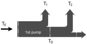
Determining the nominal value
| Flow | qv=(Vg ∙ n ∙ ηv) / 1000 | I/min |
| Torque | T=(Vg ∙ Δp) / 20 ∙ π ∙ ηmh | Nm |
| Power | P=(2π ∙ T ∙ n)/60000=(qv ∙ Δp)/600 ∙ ηt | kW |
Vg = Displacement per revolution in cm3
Δp = Differential pressure in bar
n = Speed in rpm
ηv = Volumetric efficiency
ηmh = Mechanical-hydraulic efficiency
ηt = Overall efficiency (nt= nv* nmh)
