Wenzhou Prance Hydraulic Equipment Co., Ltd

Hydraulic Valve Power-Loss States: Spring Return, Detent, and Fail-Safe Review
A hydraulic valve’s power-loss behavior depends on its restoring mechanism, hydraulic connections and available energy. A spring-return valve is intended to move toward its spring-defined position when actuation is removed; a detented valve can retain a previously selected position. Neither description alone establishes that the machine becomes safe. The load may still move, stored pressure may remain, or the hydraulic supply may continue after control power disappears. Evaluate the complete sequence from power loss through pressure changes to restart. This guide focuses on that sequence, rather than choosing a valve from the number of solenoids or a generic center-symbol chart.
Define exactly what has lost power
“Power off” can describe several different events. The controller may stop sending a command while valve electronics remain energized. The valve supply may disappear while the pump continues. The pump drive may stop while an accumulator remains charged. A pilot-operated valve can lose its pilot supply independently of its electrical supply.
These are different hydraulic boundary conditions. Record the event as a combination of signal, electrical supply, pump delivery and pilot pressure. Do not use one test in which all energy disappears simultaneously to prove the behavior of a fault that removes only the control signal.
NPTEL’s directional-valve material distinguishes flow routing from the means of actuation. That distinction is the starting point: identify what causes the valve to move and then trace what fluid can do in the resulting position. A controller’s displayed command is not direct evidence of actual spool position.
Spring return specifies an intended mechanical response
A restoring spring provides a force toward a defined position when the opposing actuation is removed. For a particular valve, that can mean an offset position or a centered state. The symbol and complete configuration determine which connections result. The phrase spring return does not necessarily mean that every work port closes.
The intended return also has operating conditions. Contamination, mechanical damage or other forces can prevent movement. A spring is not proof against every fault, and its presence does not establish a monitored safety function. Ask what the manufacturer documents for the exact valve and what the machine’s safety assessment requires.
For a pilot-operated assembly, review the main stage as well as the pilot stage. The pilot may change position while trapped pilot oil, pressure conditions or another circuit feature influences the main spool. Do not treat the visible pilot solenoid as a complete description of the assembly’s loss-of-power behavior.
Detent means retained position needs attention
A detent is intended to retain a selected mechanical position under its stated conditions. Removing the command does not necessarily produce a new neutral state. If hydraulic power remains available, the actuator may continue to receive flow in the retained direction.
This can be appropriate for some normal operating functions, but the machine designer must account for it during faults and restart. A momentary electrical command can have a hydraulic consequence lasting beyond the command itself. The control program must not assume that a zero output means all hydraulic motion has stopped.
Do not infer detent behavior from two solenoids alone. Two-solenoid valves can have different restoring arrangements, and proportional controls introduce further configuration-specific behavior. Read the complete hydraulic symbol and ordering information. Where the documentation is unclear, treat the power-loss state as unconfirmed instead of guessing from the coil count.
Trace the resulting work-port connections
Once the intended final position is known, follow P, T, A and B through the actual schematic. Are the actuator ports blocked, connected to tank, cross-connected or supplied? Does a pump-to-tank path remain? Are separate check or load-control valves still connected and functional under that state?
Blocking work ports can restrict flow without guaranteeing indefinite load holding. Connecting a port to tank can release pressure but also permit load movement. Connecting the pump to tank can unload the pump while leaving an actuator chamber pressurized. Each state solves a different problem.
Include auxiliary pilot and drain connections. A main return line and a pilot drain are not interchangeable merely because both eventually reach the tank. Backpressure and trapped pressure can change control behavior. The exact limits and permitted routing must come from the relevant component documentation.
Use an event table before choosing a remedy
The table is an engineering review framework based on directional-flow fundamentals and hazardous-energy control. It does not assign a safety category, response time or guaranteed state to any pictured product.
| Event to consider | Energy that may remain | Question the design must answer |
|---|---|---|
| Command signal goes to zero | Valve power, pump flow and stored pressure | What does the exact controller/valve combination do at zero command? |
| Valve electrical supply fails | Pump and accumulator energy | Which position is intended, and what motion remains possible? |
| Pump drive stops | Accumulator pressure, gravity and inertia | Can stored energy move the actuator or backdrive a motor? |
| Pilot supply falls | Main circuit pressure and trapped pilot oil | Does the main stage reach its documented state? |
| A work-port path closes | Load energy and trapped fluid | Are pressure and load retention controlled in that isolated volume? |
| Electrical power returns | Retained valve state and an unknown load position | What prevents unintended automatic restart? |
A useful review records the intended behavior and the evidence for each row separately. A blank or undocumented answer remains a design question even if the normal operating cycle works reliably.
cURL Too many subrequests by single Worker invocation. To configure this limit, refer to https://developers.cloudflare.com/workers/wrangler/configuration/#limits
cURL Too many subrequests by single Worker invocation. To configure this limit, refer to https://developers.cloudflare.com/workers/wrangler/configuration/#limits.
cURL Too many subrequests by single Worker invocation. To configure this limit, refer to https://developers.cloudflare.com/workers/wrangler/configuration/#limits.
cURL Too many subrequests by single Worker invocation. To configure this limit, refer to https://developers.cloudflare.com/workers/wrangler/configuration/#limits.
cURL Too many subrequests by single Worker invocation. To configure this limit, refer to https://developers.cloudflare.com/workers/wrangler/configuration/#limits
cURL Too many subrequests by single Worker invocation. To configure this limit, refer to https://developers.cloudflare.com/workers/wrangler/configuration/#limits.
cURL Too many subrequests by single Worker invocation. To configure this limit, refer to https://developers.cloudflare.com/workers/wrangler/configuration/#limits.
cURL Too many subrequests by single Worker invocation. To configure this limit, refer to https://developers.cloudflare.com/workers/wrangler/configuration/#limits.

Restart needs a deliberate state check
When electrical power returns, the machine may not be in its previous position. A detented valve may remain shifted, a spring-return valve may have moved, and the load may have coasted or settled. Sensors and pressure conditions may also disagree with the controller’s last stored state.
The restart logic should establish the required conditions before commanding motion. Depending on the design, that can include a deliberate reset, a position check and confirmation that the hydraulic supply is ready. The appropriate sequence must come from the machine’s risk assessment and control design.
Do not use an automatic return-to-home command as a substitute for checking whether that movement is safe. A recovery movement can create a hazard if someone has entered the working area or the mechanism has changed position during the outage. Restoration of supply should not be confused with authorization to resume production.

Match the review to the actual product
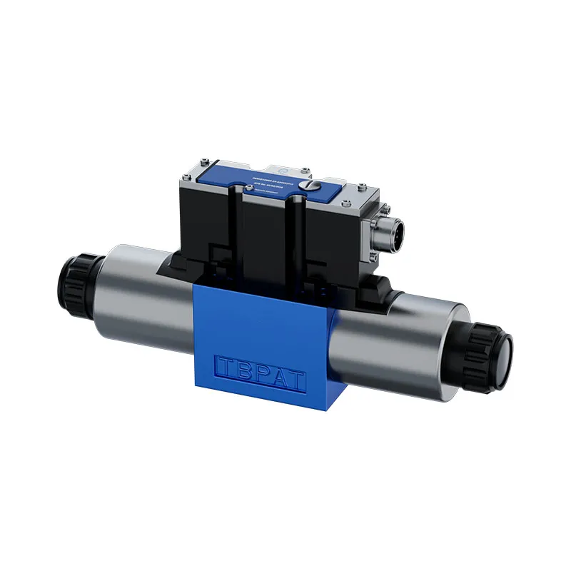
The original 4WRLE product photographs illustrate a real pilot-operated proportional-valve family. They show an exterior assembly and visible interfaces, not a certified power-loss sequence. This article does not claim that the pictured configuration has a detent, a particular spring state or an approved load-holding function.
For an enquiry, provide the complete valve code, hydraulic symbol, electrical supply, command interface, pilot arrangement and relevant schematic. Ask separately about loss of command, loss of electrical supply and loss of pilot pressure. Include the load direction, stored energy and required restart behavior.
If replacing a valve, compare these functions explicitly. A matching mounting surface, voltage or connector does not prove equivalent loss-of-power behavior. A change intended to improve normal proportional control can also change fault behavior, so review both before installation.
Verify the sequence through an approved acceptance test
Define expected behavior before testing: which valve state is intended, how much actuator movement is permitted, where pressures should be observed and what conditions require stopping the test. Testing should be planned by qualified personnel with the load controlled, the area protected and suitable instrumentation installed safely.
Test the distinct authorized events rather than improvising disconnected wires during production. Preserve the measured sequence and any unexpected motion or retained pressure. If results do not match the intended behavior, resolve the cause before normal operation; repeatedly cycling the machine is not evidence that an unexplained fault has disappeared.
The completed review should connect a specific power-loss event to a documented valve response, a controlled load outcome and a deliberate restart. That is the useful basis for a fail-safe discussion. A spring symbol or detent label is only one input to it.
Perguntas frequentes
Is every spring-return valve fail-safe?
No. Spring return describes an intended restoring action. Safety depends on the resulting flow paths, load, stored energy, possible faults and the complete machine design.
Does a detented valve return to neutral when power is removed?
Do not assume so. A detent can retain the selected position. Confirm the exact construction and its stated operating conditions.
Can I identify the power-loss state by counting solenoids?
No. Read the complete symbol and configuration information. Coil count alone does not identify springs, detents, pilot behavior or electronic response.
Why can an actuator move after the pump stops?
An accumulator, gravity, inertia or another stored-energy source may still act. Trace the available paths and follow the machine’s energy-control procedure before servicing.
What should be confirmed before a replacement valve is accepted?
Confirm normal operation, the distinct loss-of-command and loss-of-supply states, pilot behavior where applicable, load response and controlled restart. Use evidence for the exact supplied configuration.
Recursos relacionados de produto e engenharia
Válvula Proporcional Hidráulica de Ação Piloto 4WRLE, gama de produtos de válvulas hidráulicas, Como deve uma equipa de controlo escolher entre solenóides simples ou duplo?, Classificações IP do solenóide hidráulico: Bobina, Conector e Proteção instalada. Confirme o código completo do produto e os requisitos da aplicação ao solicitar uma revisão de configuração.
Referências técnicas
Further learning: hydraulic valves
5.4 – Directional Control Valves by NPTEL-NOC IITM provides background on directional valve construction and flow routing. The directional-valve lesson supports tracing control actuation and flow routing; complete machine power-loss behavior must still be established from its configuration. It supplements the component fundamentals; it is not a test procedure for the complete circuit discussed above.