Wenzhou Prance Hydraulic Equipment Co., Ltd

Hydraulic Motor Replacement Checklist for Mobile Equipment
A hydraulic motor replacement checklist should verify the failure cause, ordered configuration, mechanical fit, hydraulic connections and commissioning result. The replacement is not complete when the motor is bolted in place. Confirm drain routing, shaft engagement, rotation, brake behavior and operating measurements before returning the machine to service. Preserve the old component and its operating evidence until the investigation is complete.
This checklist is intended for mobile-equipment maintenance and procurement. It explains what to record at each stage and how to avoid reinstalling the condition that damaged the original motor. Component-specific procedures and limits remain part of the selected motor's documentation.

Record the problem before removing the motor
Write down the original symptom, when it occurs and what maintenance preceded it. Include pressure, speed, temperature, drain flow and case pressure where a safe test is possible. A stalled shaft can result from a brake, valve, load or coupling problem rather than a failed motor. Establish what is confirmed before buying a replacement.
Photograph the nameplate, installed port connections, mounting position and driven equipment. Label the hose functions against the hydraulic drawing. Preserve any operating logs and fault messages. If the motor cannot be safely run, record that limitation rather than trying to obtain measurements under hazardous conditions.
Identify the complete original configuration
Capture every available ordering-code character and the relevant drawing revision. Product-family names can omit shaft, seal, port, brake, bearing or control options. Compare the actual installation with the drawings because previous repairs may have changed adapters or assemblies. Do not let an unreadable suffix become an assumed standard option.
Record the machine serial or configuration identifier and the motor's role. Several motors on one machine can have similar housings but different duties. For fleet replacement, verify each machine's circuit and mechanical interface instead of assuming that one order code covers every unit.
Confirm the replacement specification
Compare required torque, speed, pressure difference and duty with the proposed motor's documented performance. Include startup, reversal and load-driven braking if applicable. A matching displacement is helpful but insufficient. Confirm continuous and short-duration limits under the actual oil and temperature conditions.
Review mounting, shaft, housing envelope and external-load capability. If the supplier proposes an alternative rather than the original code, require a marked comparison of matches and differences. Identify adapters or circuit changes explicitly. A candidate remains unapproved while important dimensions, drain requirements or control behavior are unresolved.
Prepare safe removal and handling
Follow the machine's energy-isolation procedure, support loads and release stored pressure. Hydraulic pressure can remain trapped in lines or accumulators after the power source is off. Verify the relevant isolation points before disconnecting. Plan lifting and support for the motor and any attached valve block or brake assembly.
Clean around connections and have suitable caps and plugs ready. Mark hose destinations using their verified function rather than ambiguous left-and-right labels. Keep dismantled parts identified and protected. Do not leave open hoses where dirt, water or metal debris can enter during the time the machine is awaiting a replacement.
Inspect the machine-side interfaces
Check the mating flange, pilot bore, bolts, shaft coupling or splines and the driven equipment. A damaged hub or misaligned bracket can harm the replacement. Record wear, cracks, fretting and evidence of axial bottoming. Use the applicable drawing and repair criteria rather than accepting a part because it still assembles.
Review belt tension, chain pull, wheel offsets and other external shaft loads. If a component change moved the load outward, confirm the overhung moment. Do not treat the replacement motor as a way to compensate for an incorrect mechanical arrangement. Resolve the load path before installation.
Address contamination from the failure
Determine whether the failed motor released debris into the circuit and which components may have been exposed. Review oil and filter evidence and the circuit flow paths. A bearing or rotating-group failure can require more extensive cleaning than an external fitting leak. The cleaning scope should follow the failure evidence and the machine instructions.
Use an approved cleaning or flushing procedure and verify the fluid condition before connecting the new motor. Avoid running contaminated oil through the replacement as an improvised flushing method. Retain samples and cleaning records where required. If contamination is only suspected, distinguish that suspicion from confirmed debris when writing the service report.
Check the incoming component before modification
Compare the delivered nameplate and full ordering code with the approved order. Inspect shipping protection, port plugs, shaft, flange and housing for damage. Measure the agreed critical interfaces using the stated datums. Do not force a hub onto the shaft to test an unidentified fit.
Keep discrepancies documented before altering the motor. Changing fittings may be part of an approved installation, but grinding a pilot, modifying splines or opening the motor to make it fit should not become an informal receiving procedure. Resolve incorrect supply through the agreed acceptance process.
Use a staged replacement checklist
| Palco | Checks to complete | Record to retain |
|---|---|---|
| Before removal | Failure symptoms, model code, hose functions and isolation | Photos, drawing references and safe-test readings |
| After removal | Machine mounting, coupling, shaft loads and contamination | Inspection findings and cleaning scope |
| On receipt | Delivered code, damage and critical dimensions | Incoming inspection and supplier documents |
| During installation | Flange seating, engagement, alignment and drain route | Assembly checks and configuration photos |
| First movement | Oil fill, low-risk rotation and brake sequence | Initial commissioning observations |
| Loaded acceptance | Pressure, speed, temperature, leakage and realistic duty | Signed acceptance data and unresolved items |
An incomplete stage should not be marked finished because the next stage is urgent. Resolve the missing information or document the specific limitation before returning the machine to service.
Install without damaging the shaft or seals
Use the specified handling and assembly procedure. Protect shaft seals from keys, splines and sharp edges while fitting associated parts. Apply hub installation forces correctly and avoid passing unintended loads through the motor bearings. Confirm the axial spacing and usable engagement before tightening the mounting.
Ensure the flange seats fully and the mounting does not distort the housing. Use the specified fasteners and tightening procedure. Recheck alignment after final tightening and after hoses are secured. A neat visual installation can still contain shaft thrust, offset or a partially seated pilot.
Restore the correct hydraulic paths
Connect work ports, drain, brake release, flushing and controls according to the approved schematic. Identify thread and sealing standards rather than using fittings that merely appear to engage. Check actual passage restrictions, hose bend radius and service access. A drain line must reach its approved destination without exposing the housing to unapproved pressure.
Restore the required housing fill and startup preparation. Confirm that a quick coupler is fully connected where one is used. Do not assume that the new motor's port arrangement matches the old unit because the housing looks similar. Update labels and drawings for any approved change.
Verify first movement under controlled conditions
Use the machine's approved commissioning sequence with personnel clear of moving parts. Confirm the observation side for clockwise or counterclockwise rotation and the resulting machine travel. Check brake release before demanding useful motion. If rotation is wrong or a brake drags, stop and isolate before correcting connections.
Record pressures and case conditions at reduced duty, then increase speed and load in controlled steps. An unloaded spin confirms only part of the installation. It does not validate full torque, external shaft loads or braking behavior. Keep the test configuration clear in the report.
Reproduce the original demanding duty safely
Acceptance should cover the conditions associated with the original failure: cold start, warm continuous operation, reversal or simultaneous machine functions. Capture the relevant measurements together so an abnormal event can be connected with its cause. Compare results with the selected motor and machine limits, not with an unrelated model.
Inspect for leakage, unusual temperature rise, vibration and unstable movement. If an unresolved symptom remains, do not report the replacement as a successful root-cause repair. Identify what passed, what failed and which measurement or review is required next. The goal is reliable service, not simply a completed parts exchange.
Close the maintenance and purchasing records
Record the removed and installed motor codes, approved changes, installation date and acceptance result. Keep the supplier's drawings, limits and any interchange comparison with the machine history. Retain the failed part until warranty or root-cause requirements are satisfied, and do not discard it without authorization.
Define follow-up checks according to duty and risk. A useful baseline includes the actual operating conditions, not just a single temperature number. Future maintenance should be able to reproduce the comparison and identify whether the machine is changing before another major failure.
Perguntas frequentes
Should I order the same motor before investigating the failure?
Establish the configuration and likely cause first where practical. The same motor may be appropriate, but an unchanged drain, load or contamination problem can damage it again.
Is a successful unloaded test enough to return the machine to service?
No. Verify the relevant loaded duty, pressures, temperatures, braking and leakage. An unloaded direction check is only an initial commissioning step.
Can old adapters be reused?
Only after confirming their standards, condition, seals, rating and suitability for the replacement. A reused restrictive drain adapter can transfer the original problem to the new installation.
What if the new motor needs different plumbing?
Document and approve the circuit and adapter changes before installation. Update the port map and test the resulting restrictions and behavior under realistic duty.
What should be included in the final service report?
The old and new configuration, confirmed failure findings, corrective actions, installation checks and operating acceptance evidence. Clearly identify any remaining uncertainty rather than recording a blanket pass.
Produtos e recursos de engenharia relacionados
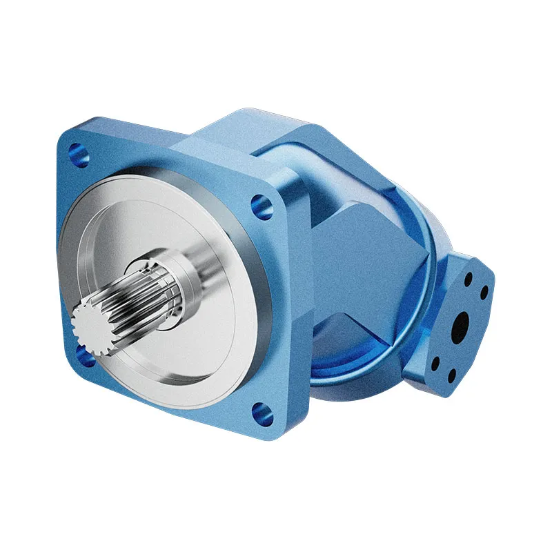
Para uma consulta sobre um componente, consulte Motor de pistões de eixo fixo e inclinado AA2FM e forneça a especificação completa e as condições de instalação. Guia relacionado: Área de atuação do motor de pistão, Faixa de alcance do motor orbital, Verificações de pressão no motor, Medição de vazão de drenagem do motor, Calculo da eficiência do motor, Guia de troca de motor hidráulico: o que deve corresponder, Hydraulic Motor Factory Test Report: Torque, Speed, and Leakage. As fotografias dos produtos ilustram as configurações do catálogo; elas não estabelecem a classificação de pressão, velocidade ou carga axial para um pedido não confirmado.
Conferência universitária: fundamentos do motor hidráulico
O NPTEL-NOC da IITM apresenta uma aula sobre motor hidráulico do IIT Madras. A apresentação apoia a distinção entre a entrada hidráulica e a saída do eixo, conforme descrito neste guia. As limitações de instalação e operação específicas dos componentes ainda exigem a documentação do motor selecionado.
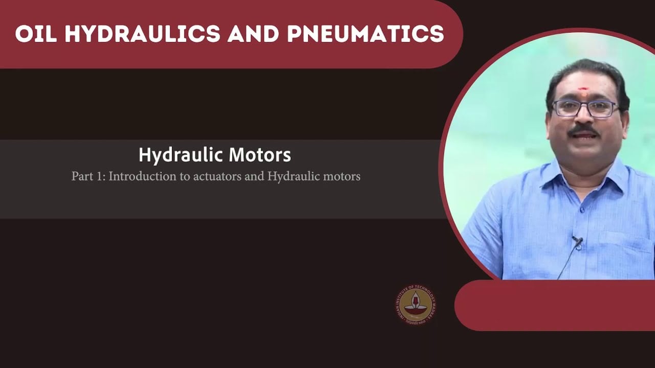
Aprenda mais sobre os motores hidráulicos no NPTEL.
Referências técnicas e de segurança
- NPTEL: Fundamentos de Hidráulica e Pneumática Industrial
- NIOSH: prevenção de lesões causadas por energia perigosa
- Referências técnicas: princípios de funcionamento e instalação de motores orbitais
Essas referências fornecem contexto educacional e técnico. As classificações específicas de um modelo de fabricante não constituem especificações para um produto da Prance e não implicam filiação ou autorização à marca.