Wenzhou Prance Hydraulic Equipment Co., Ltd

Hydraulic System Preventive Maintenance Schedule: Daily to Annual Checks
A hydraulic system maintenance schedule should combine routine observations, operating-hour tasks and condition-triggered work. Begin with the machine and component manufacturers' instructions, then assign an owner, inspection method, action limit and record to every task. Daily checks help reveal changes in oil level, temperature, leakage and machine behavior; periodic reviews assess fluid condition, filtration and component performance. A calendar alone cannot determine when oil, a pump or a valve needs replacement. The useful schedule connects each observation to a safe decision, including when to stop the machine and how to verify it before returning to production.
This guide gives maintenance planners, equipment buyers and service supervisors a practical framework. The calendar below is a starting template, not a manufacturer-approved service interval for a particular Prance product. Use the exact ordered pump, motor and valve documentation to set limits and permitted procedures.
Establish the equipment boundary and responsibilities
Start with a circuit drawing and a component register. Identify the power unit, pumps, control valves, actuators, accumulators where fitted, filtration equipment and any separate cooling or lubrication circuits. Record which components share fluid and which have independent reservoirs. Otherwise, a sample or temperature reading may be assigned to the wrong system.
For each item, record its identification, ordered configuration, approved fluid, applicable instructions and available measurement points. A catalogue family name is insufficient when a pump can have different shaft, port or operating configurations. Keep supplier drawings with the register so a replacement enquiry can refer to the installed equipment rather than an approximate photograph.
Assign responsibility separately for observation, interpretation and servicing. An operator can report a changing sound or visible leak without being authorized to adjust a compensator or disconnect a pressurized hose. State which tasks require trained maintenance staff, electrical competence, a planned shutdown or a documented isolation procedure. This prevents a simple checklist from becoming an invitation to unsafe intervention.
Build a repeatable healthy baseline
Record representative operating conditions when the system is known to function correctly. Include load, selected speed, operating mode, fluid temperature, pressure at defined points and any available flow measurements. Measure at comparable conditions on subsequent visits; an unloaded cold reading should not be compared directly with a loaded warm baseline.
Describe the measurement method and instrument identity. For example, state whether a pressure value comes from a local gauge, a calibrated transducer or the machine display. Note the measurement location and whether the reading is steady or transient. Useful trends require consistent methods, not just a growing spreadsheet of numbers.
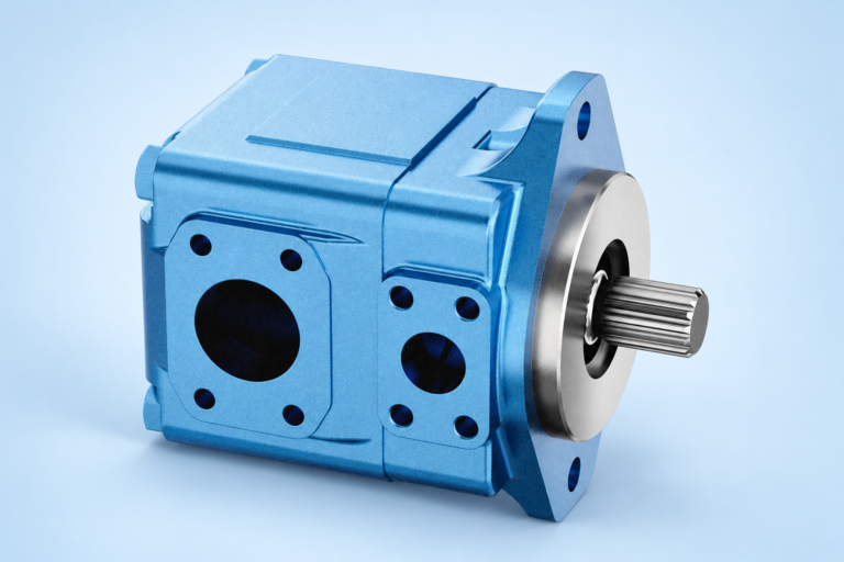
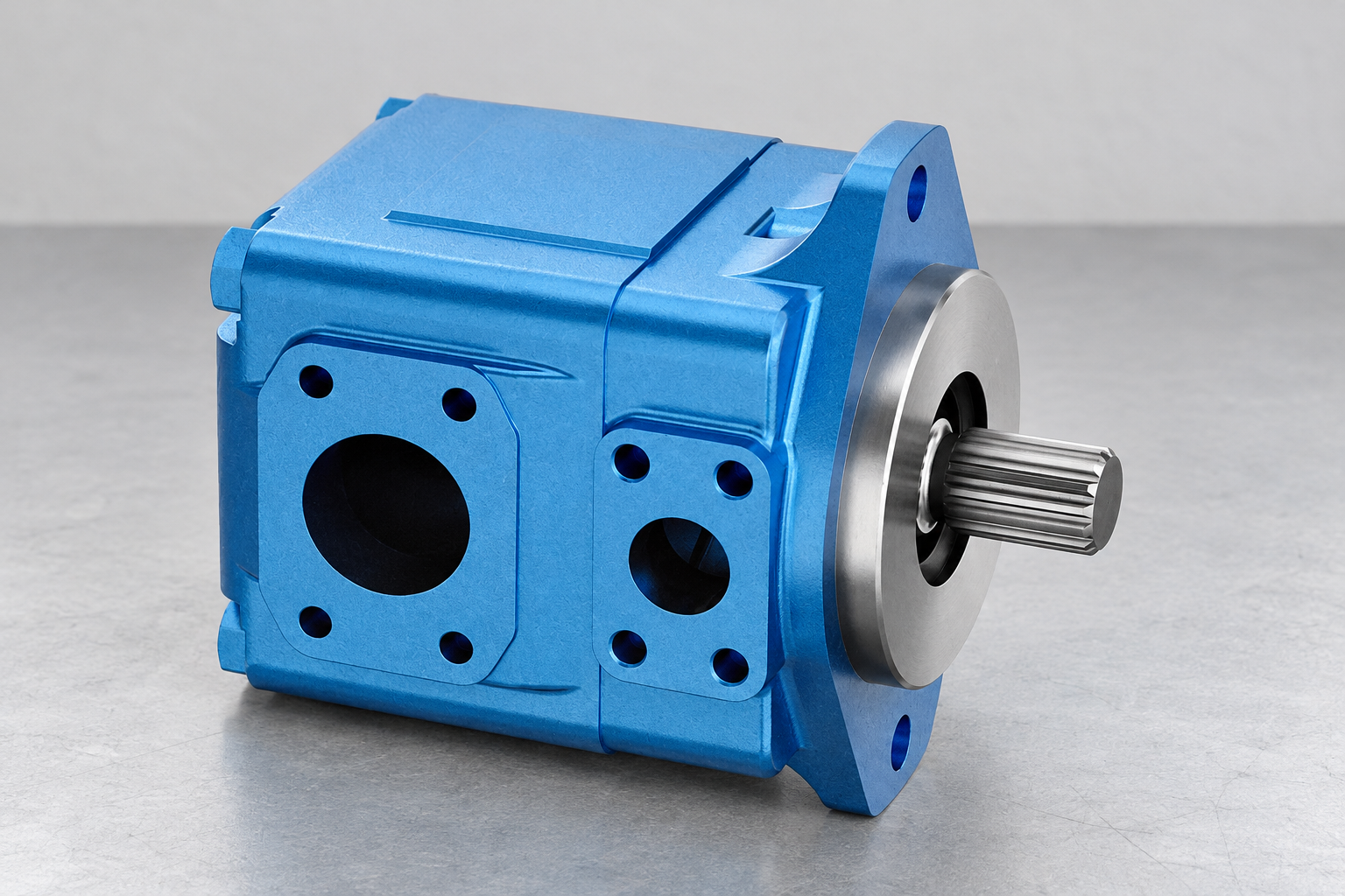
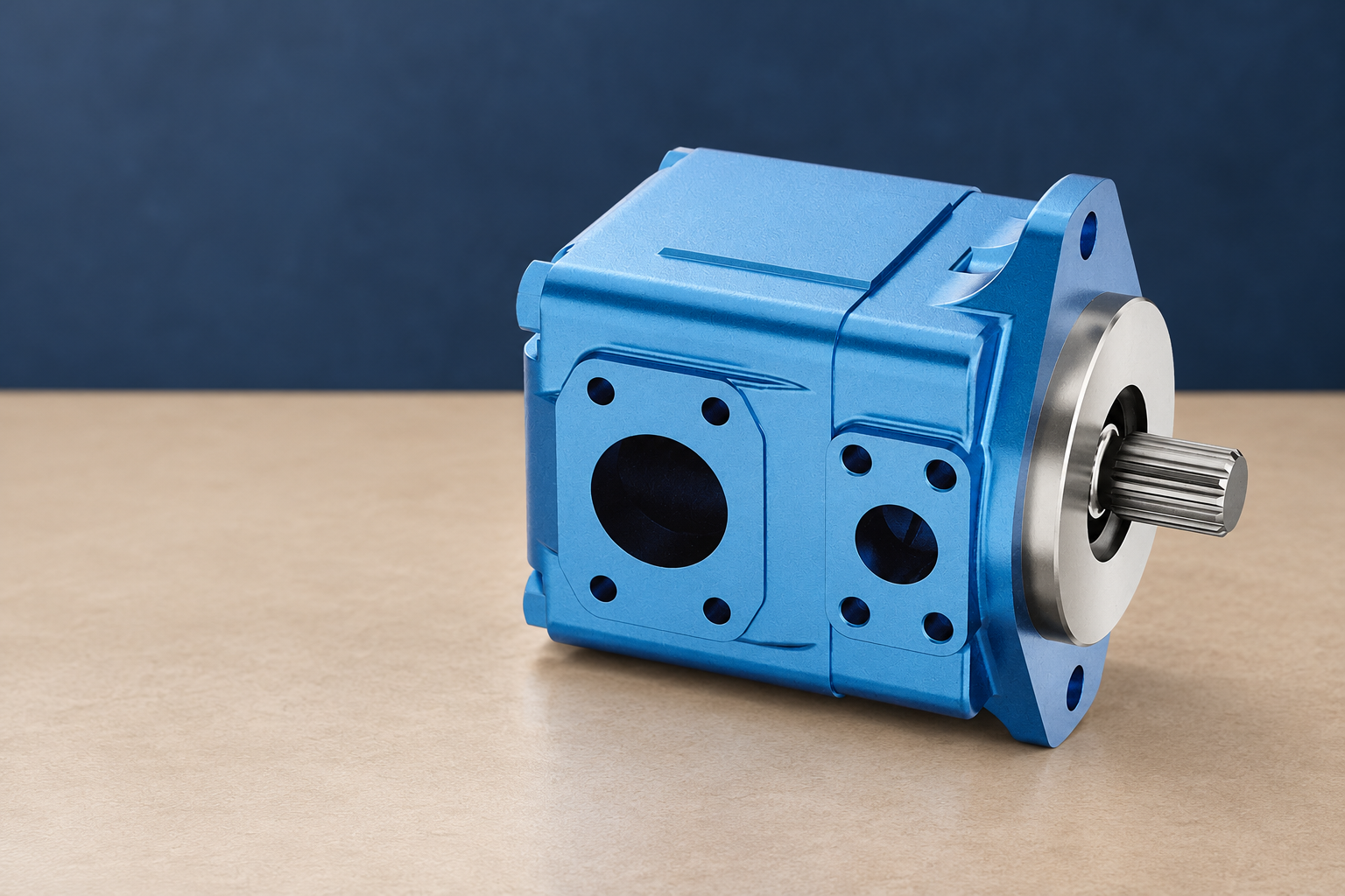
A baseline also includes photographs of external condition, documented leaks, connector condition and accessible component interfaces. Photograph only safe, stationary inspection conditions. An external pump image can help identify the component and its ports, but it cannot establish internal wear, cleanliness or remaining service life. Treat images as identification evidence alongside measurements and documentation.
A daily-to-annual planning template
The following schedule organizes work by review frequency. Replace these starting frequencies with the applicable OEM requirements and a documented assessment of operating hours, contamination exposure, consequence of failure and actual trends. A calendar review does not automatically mean fluid or component replacement.
| Planning frequency | Practical checks or reviews | Record and decision |
|---|---|---|
| Each operating day or shift | Observe permitted oil-level indication, temperature trend, visible leaks, unusual sound and changed motion | Record operating state and change from baseline; escalate unsafe leakage or abnormal behavior immediately |
| Weekly planning review | Review open defects, accessible hose routing, supports, connector condition and filter-indicator observations | Assign an owner and due date; separate observation from any adjustment requiring isolation |
| Monthly or hour-based review | Review representative fluid-analysis trends, filter performance and loaded pressure or flow measurements where specified | Compare like-for-like methods and component-specific limits; investigate trends before ordering replacements |
| Planned quarterly or seasonal review | Review duty changes, cooling performance, contamination entry points and condition of critical component interfaces | Revise inspection frequency if duty or environment changed; document required shutdown work |
| Annual planning review | Review failure history, supplier instructions, spares, instruments, emergency procedures and return-to-service records | Update the schedule and equipment register; retain justified tasks and remove redundant observations |
| Condition-triggered intervention | Respond to confirmed contamination, sudden temperature rise, unsafe leakage or a material performance change | Apply the machine-specific stop or isolation procedure; diagnose the cause and establish release criteria |
Supporting technical context: NPTEL: industrial hydraulic fluids and component principles, NIOSH: prevenção de lesões causadas por energia perigosa. This evidence checklist does not establish a product rating or universal acceptance limit.
Add operating-hour triggers alongside dates. A machine running continuously and one running occasionally should not receive identical service assumptions simply because both were installed in the same month. For critical tasks, specify which trigger governs when both calendar and hour limits exist.
Daily observations that lead to clear action
Read fluid level only in the machine state specified by its instructions. Actuator position, thermal expansion and retained fluid in the circuit can change the indicated level. Record the state rather than repeatedly topping up to an arbitrary mark. Unexplained fluid loss should become a defect investigation; adding oil does not repair a leak.
Temperature should be interpreted with load, ambient conditions and warm-up state. A rising trend under comparable duty can justify investigation of losses, cooling, fluid condition or control behavior. It does not identify a failed pump by itself. Use the applicable fluid and component limits for action, and avoid imposing a generic temperature threshold on every system.
Observe accessible hoses and fittings from a safe position. Do not use a hand to search for a pressurized leak, and do not tighten a connection on a live system. Where the machine has guarded or inaccessible sections, define the permitted observation method. A checklist item should never require bypassing guarding to obtain a convenient photograph.
Record changed movement as a symptom with context: load, direction, speed command and whether the change appeared suddenly or gradually. Slow movement, drift or vibration can have several causes. A short, precise symptom record makes the next diagnostic step more useful than a general instruction to replace the most visible component.
Pump, motor and valve tasks need different evidence
For a pump, track the permitted inlet-condition observations, output performance and any case-drain measurements required by its design. Keep suction-related observations distinct from discharge pressure. A normal discharge gauge does not establish that inlet conditions are suitable. Use the selected pump's instructions to decide which measurements are meaningful and how they can be performed safely.
For a hydraulic motor, record duty, speed, load behavior, accessible external leakage and any required drain-flow trend. Drain-flow interpretation depends on temperature, pressure, motor design and the measurement arrangement. A change under comparable conditions may justify investigation, but an unsupported universal drain-flow limit should not determine replacement.
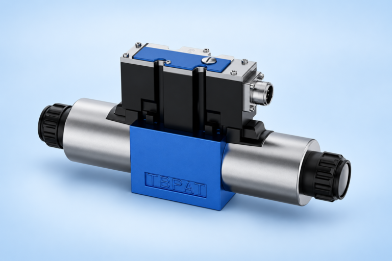
For a valve, identify the circuit function before assigning maintenance checks. External cleanliness, connector condition, command behavior and operating response may be relevant to an electrically controlled directional valve. They do not establish a relief setting, pilot ratio or pressure-control function that the installed valve does not have. Keep the circuit symbol and configuration with the task.
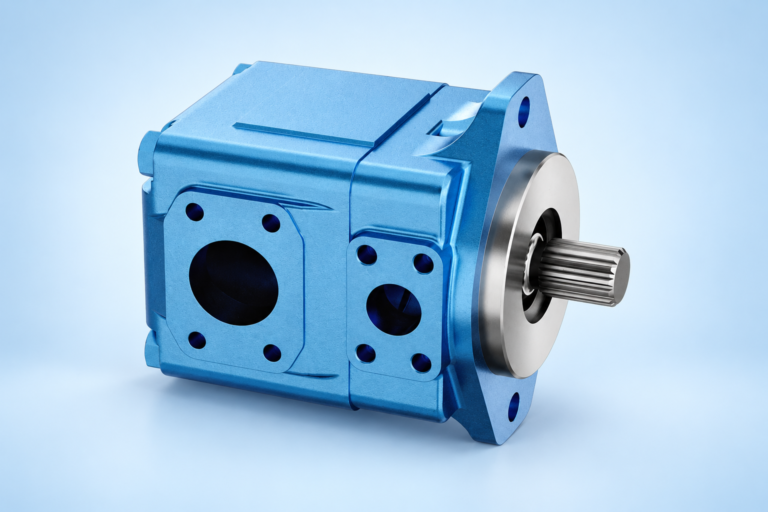
The Prance T6 vane-pump catalogue image used here supports external component identification. It is not evidence of an installed machine's safety condition or an instruction to open the pump. Ask for configuration-specific limits, drawings and servicing instructions when creating the final work order.
Fluid analysis and filtration belong in a trend program
Define where a representative fluid sample can be taken, the required operating state and the laboratory method. Follow the approved sampling procedure and use suitable clean containers. Record the sampling point and recent maintenance, top-ups or fluid changes so an unexpected result can be interpreted in context.
Choose tests according to the fluid and failure risks, with laboratory and OEM guidance. Particle counts, water assessment, viscosity or other tests answer different questions. One satisfactory result does not establish that every aspect of the fluid is acceptable. Keep the method and reporting units consistent when comparing results over time.
Filter maintenance should follow the specified element, indicator interpretation and permitted operating conditions. Review unusual restriction or repeated element changes as possible evidence of a wider problem. Changing a filter without addressing contamination entry, wear debris or an incorrect element can leave the cause in place. Never bypass filtration simply to restore apparent flow.
Plan fluid changes from applicable instructions and condition evidence rather than adopting a search-result interval as a universal rule. When changing fluid type or supplier, confirm compatibility and the approved procedure. Document the product identity and batch where appropriate; similar viscosity labels alone do not prove full compatibility.
Turn exceptions into work orders
A useful defect record contains the observation, evidence, operating state, risk assessment, responsible person and next action. Distinguish a confirmed defect from a suspected cause. For example, record the measured temperature change before naming internal leakage as the explanation. This preserves a clear diagnostic trail.
Prioritize by consequence and confidence. Unsafe leakage, unexpected movement or failed protective behavior requires the machine-specific response. A gradual performance trend may allow a planned investigation, depending on the equipment and risk. Define escalation in the maintenance system so operators do not have to invent a threshold during production.
Set a completion condition before ordering parts. A work order to investigate overheating might require verification of the actual duty, pressure losses, cooling performance and fluid condition. A work order to replace a component needs the approved specification and a return-to-service test. The objective is a corrected failure mechanism, not merely a closed ticket.
Plan shutdown work and control stored energy
Hydraulic systems can retain hazardous energy after the electrical supply is switched off. Accumulators, supported loads and trapped pressure may require separate controls. Follow the machine-specific energy-isolation procedure and verify the required safe condition before any task involving disconnection, adjustment or access to hazardous parts.
The NIOSH hazardous-energy guidance supports the need for isolation and verification. It does not replace the machine's procedure, training or applicable workplace requirements. Record which personnel are authorized to perform the work and how the equipment will be protected against an unexpected restart or movement.
Prepare clean parts, correct tools, approved fluids and identified connections before opening the circuit. Protect open interfaces using the approved method. Keep removed parts and inspection evidence where a failure investigation is necessary. Avoid mixing diagnosis with an undocumented series of adjustments that changes the baseline and obscures the original fault.
Verify before returning the machine to service
Check the completed work against the drawing and work order. Confirm the component configuration, connections, fluid identity, guarding and required documentation. Conduct the approved start-up and test sequence, keeping personnel clear of hazards. Recheck for leakage and abnormal behavior at the permitted stages rather than assuming successful assembly proves safe operation.
Record pressure, flow, temperature and functional results under defined conditions where required. Compare them with the applicable acceptance criteria and the healthy baseline. If a result is outside the approved limit, reopen the work order and investigate; a replacement component does not automatically resolve a system-level problem.
Update the maintenance record with the actual findings, parts, fluid additions and any changed settings that were authorized. Retain before-and-after measurements and supplier documents. Use the review to revise task frequency when evidence justifies it, while preserving mandatory OEM requirements. This is how the schedule becomes more accurate without turning every minor observation into unnecessary component replacement.
Procurement information that improves maintenance planning
When requesting a replacement pump, motor or valve, provide the installed identification, drawings, fluid, operating conditions and observed failure evidence. Include the required interfaces and circuit role. A matching external appearance is insufficient to establish interchangeability, control behavior or operating limits.
Ask the supplier for the applicable installation, operating and maintenance documents for the ordered configuration. Keep those documents with the equipment register, and make their limits available to the staff doing the checks. This links purchasing decisions to reliable maintenance and avoids losing essential instructions after the component arrives.
Perguntas frequentes
How often should a hydraulic system be inspected?
Use the machine and component instructions first. Daily or shift observations can reveal changing level, temperature, leakage and behavior, while periodic work should reflect operating hours, duty, environment and consequences of failure. The example calendar is a planning framework, not an approved service interval for every machine.
Does an annual review require replacing all hydraulic oil?
No. An annual review can assess fluid-analysis trends, service history and the applicable instructions. Fluid replacement should follow the approved requirements and condition evidence. Calendar age alone does not establish suitability, and a satisfactory result from one test does not establish every aspect of fluid condition.
Can a pump photograph confirm whether maintenance is needed?
A photograph can document visible condition and help identify external interfaces. It cannot establish internal wear, operating efficiency or cleanliness. Combine identification with representative measurements, operating history and configuration-specific instructions before deciding whether a pump requires investigation or replacement.
What should trigger an unscheduled maintenance task?
Confirmed contamination, unsafe leakage, unexpected motion, abrupt performance changes or a significant trend outside the applicable limits can trigger action. Use the machine-specific escalation and isolation rules. Record the observed evidence separately from the suspected cause so the subsequent investigation remains reliable.
What records should be kept after a hydraulic component replacement?
Keep the ordered configuration, supplier documents, work performed, approved fluid identity, authorized setting changes and return-to-service results. Include the measurement locations and operating conditions. These records support future comparisons and show whether the repair corrected the problem instead of simply replacing a part.
Related products and engineering guides
T6 vane pump catalogue, vane pump product range, pump contamination control, Medição de vazão de drenagem do motor. Provide the circuit, fluid, duty and exact ordered configuration when requesting component-specific data.
University lesson: mod-40 lec-42 AppendicesTutorial on Basic Calculation on HST System and Hydraulic Fluids
This NPTEL university lecture explains hydraulic-fluid properties and hydraulic power calculations, which explain why maintenance records need consistent fluid identity, load, temperature and efficiency context. It does not prescribe maintenance intervals or demonstrate servicing.

Technical references
- NPTEL: industrial hydraulic fluids and component principles
- NIOSH: prevenção de lesões causadas por energia perigosa
Sources support the stated principles and method scope. Illustrative inputs and another manufacturer’s documents do not establish Prance component ratings, warranties or brand affiliation.