Wenzhou Prance Hydraulic Equipment Co., Ltd

Hydraulic Valve Null Adjustment: Servo and Proportional Controls
What hydraulic valve null adjustment can change
Hydraulic valve null adjustment establishes a specified neutral operating point for a particular servo or proportional valve and its control electronics. It must follow the exact manufacturer's procedure. Depending on the design, an adjustment can concern electrical offset, spool-position calibration or hydraulic balance; these are not interchangeable operations. Do not turn an unidentified screw to stop cylinder drift. Drift can result from actuator leakage, load-related pressure, incorrect commands or other circuit faults. First identify the complete valve and driver, establish the intended neutral condition and measure the relevant signals. A successful adjustment preserves stable neutral behavior without concealing another fault or creating unintended actuator movement.
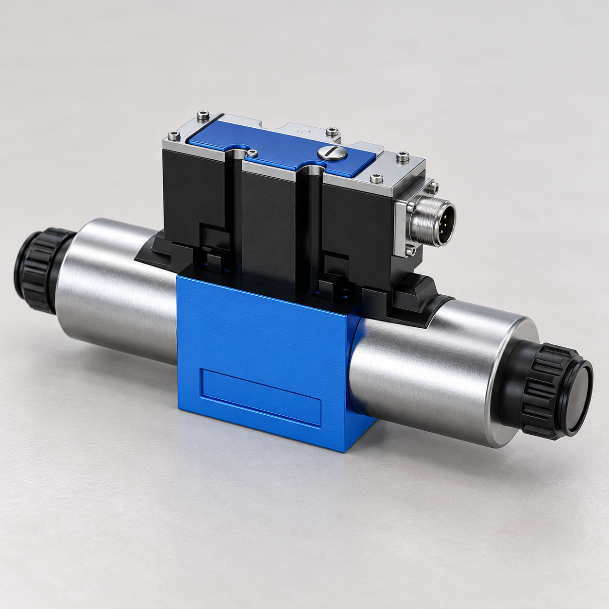
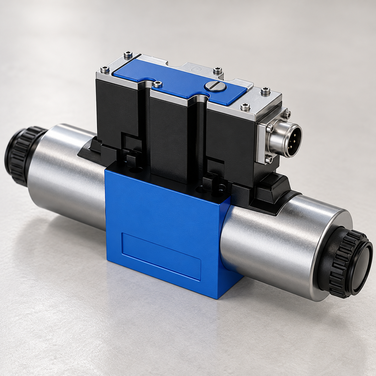
A photograph of a valve does not establish whether its null is adjustable in the field. Some assemblies require factory calibration or an approved service arrangement. Integrated electronics can also contain calibration values whose meaning differs from a user-configurable command offset. An article can help organize diagnosis, but it cannot replace model-specific instructions for an internal or sealed adjustment.
Define neutral before evaluating a fault
Neutral is a specified state, not a universal absence of every flow or pressure. A directional valve's center configuration determines which ports connect, block or communicate through metering paths. A servo valve can have a specified leakage characteristic even when its external command is at the nominal neutral value. Review the symbol and configuration before deciding that an observed flow proves incorrect null.
Define the command neutral, expected feedback and relevant hydraulic result. Name the measured ports and state supply and load conditions. When a controller operates a closed loop, its output may be nonzero while maintaining a target position against disturbances. That output should not automatically be interpreted as an incorrect valve neutral.
Separate the machine's safe holding function from the valve's neutral calibration. A spool valve may not be the designated load-holding device. An actuator with an external load can move because of leakage elsewhere in the circuit. Altering null to counteract that motion can leave the underlying hazard unchanged and create a different response when the load or temperature changes.
Identify which adjustment the documentation describes
An electrical offset shifts the relationship between a command and an electronic reference. A spool-position calibration establishes the relation between a sensor and the controlled mechanism. A hydraulic null procedure concerns a defined hydraulic balance or output. These descriptions explain why one adjustment cannot be assumed to correct every neutral symptom.
Record the exact assembly, electronics version and approved parameter interface. Note any software limits, access restrictions and required service equipment. Confirm whether the procedure applies to a complete valve assembly or only to a separately identified driver. A parameter named zero on a machine screen can concern an actuator sensor rather than the valve.
If instructions require a specific test circuit, fluid condition or instrument, obtain those prerequisites before proceeding. Do not substitute a loaded production machine simply because it is convenient. A method intended for a service bench may be unsafe or uninterpretable in a different circuit. Keep the original configuration recoverable and document who is permitted to make the adjustment.
Check the command and electrical interface first
Measure the relevant signal through the approved interface. Confirm polarity, scaling, reference connection and the neutral command generated by the controller. Noise, a poor reference or a scaling error can create a small unintended command. Adjusting the valve around that erroneous signal can make it appear satisfactory until the signal path is repaired.
For current-regulated or integrated electronics, do not use an unloaded voltage reading as a complete test. Record the driver state and any diagnostic information supported by the exact system. Check power and return connections according to the equipment's procedures. Avoid opening a live connector or probing an interface in a way that compromises sealing or creates a short circuit.
Compare the controller command with the signal that reaches the valve electronics. Communication settings or intermediate devices may change the command or maintain a stored value. Where permitted, a controlled reference input can help separate the command source from the valve. Such a test requires deliberate isolation of normal machine control and prevention of unintended motion.
Separate valve behavior from cylinder drift
Record the actuator's direction and rate of drift, pressures and load condition. Confirm that the position measurement is reliable. A drifting position signal can create an apparent motion problem or cause a closed-loop controller to issue an unnecessary corrective command. Check the measurement chain before changing hydraulic calibration.
Investigate actuator and circuit leakage using an approved diagnostic arrangement. A cylinder seal, valve leakage path and load-holding component produce different faults, and their symptoms can overlap. Use pressure and flow evidence to separate them. Do not loosen a pressurized fitting or block a line arbitrarily to identify a leak path.
A command offset that temporarily stops drift is not proof of a successful null adjustment. It can simply deliver enough compensating flow to oppose leakage. If the machine changes load, temperature or direction, the same offset may cause motion. Treat the need for substantial compensation as diagnostic evidence rather than a reason to keep increasing the adjustment.
| Neutral symptom | Evidence to collect | Appropriate next decision |
|---|---|---|
| Nonzero input reaches the valve during commanded neutral | Controller output, interface scaling and signal reference | Correct the command path before calibrating the valve |
| Feedback is offset but hydraulic behavior matches the specified center | Sensor identity, calibration information and approved diagnostic values | Confirm whether feedback calibration is required |
| Actuator drifts with the specified valve input | Port pressures, circuit symbol and approved leakage measurements | Separate actuator, valve and holding-function leakage |
| Neutral behavior changes strongly with temperature | Fluid temperature, electronics condition and repeated traces | Investigate condition dependence before accepting a fixed correction |
| Adjustment causes sudden movement near zero command | Before-and-after mapping and neutral transition trace | Restore the safe baseline and review the permitted procedure |
| Procedure requires sealed internal access | Exact service documentation and authorized facilities | Use the specified service route rather than improvising |
For the control principles behind these distinctions, see NPTEL servo and proportional valve teaching. This decision table is not a product specification.
These are diagnostic choices, not instructions to move internal parts. Use the exact component documentation and hazardous-energy procedures before any measurement or adjustment involving a moving or pressurized machine.
Prepare an authorized adjustment safely
Save the original parameter file and baseline traces. Record the complete valve identity, circuit diagram, instrument locations, fluid condition and electrical configuration. State the symptom being corrected and the success criterion. A change should have a defined purpose beyond making one gauge or display read zero.
Isolate hazardous energy according to the machine's procedure. Electrical isolation alone does not remove stored hydraulic energy or gravitational loads. Secure the actuator and establish the permitted testing conditions before reapplying energy. Only qualified personnel should conduct an energized test that the approved adjustment procedure requires.
Use the adjustment sequence and limits specified for the exact assembly. Change one approved parameter at a time and record the direction and magnitude of the change. Avoid disturbing seals, factory settings or mechanical elements that the procedure does not authorize. If the instructions are unavailable or contradictory, stop that adjustment and obtain the required information.
Verify the result beyond one stationary condition
Repeat the documented neutral test under the required conditions. Record both hydraulic output and relevant electrical or feedback signals. Check approach from both command directions when the procedure requires it. A result reached from one direction may differ after the valve has moved in the opposite direction.
Verify the transition out of neutral. A setting that improves stationary behavior can create abrupt startup or an uneven directional response. Check the machine's permitted operating range and the applicable controller behavior, including enabled and disabled states. Do not remove interlocks or protective functions merely to make a test easier.
Check the effect of approved temperature and load variations. A fixed calibration cannot be assumed valid beyond the conditions under which it was verified. If the required operating range cannot be tested, record the limitation and arrange the remaining verification before accepting the machine for that duty.
Avoid confusing null, deadband and gain
Null adjustment sets an operating reference. Deadband concerns an input interval without a significant selected output change. Gain concerns the relation between an input change and an output change outside that interval. They can interact, but they answer different engineering questions.
Increasing gain to overcome an incorrect neutral reference can cause excessive sensitivity elsewhere. Shifting null to reduce the apparent inactive interval can create unwanted neutral flow. Changing several parameters simultaneously hides the cause of an improvement and makes the final configuration difficult to reproduce.
For a feedback-controlled valve, internal control may already manage spool position using factory calibration. Adding an external correction without understanding that architecture can make the machine controller fight the valve controller. Review the permitted interface and adjustment responsibilities instead of treating every valve as an open-loop device.
Record a useful service and purchasing report
A report should identify the original symptom, diagnostic measurements, approved procedure, initial settings, final settings and verification conditions. Include raw traces and instrument information where timing or small offsets matter. Record any untested operating condition and any separate circuit fault that remains unresolved.
For a replacement enquiry, provide the complete valve code, center symbol, electrical interface, control architecture and required neutral behavior. Ask whether field null adjustment is permitted and what equipment is required. Clarify the supplied calibration and the responsibilities for machine commissioning.
Do not accept interchangeability from mounting dimensions alone. A mechanically compatible valve can differ in neutral paths, leakage, command scaling or feedback behavior. Preserve the circuit's intended function and evaluate the replacement using documented conditions. A new assembly should not be adjusted to imitate an unidentified fault in the old assembly.
Perguntas frequentes
Can null adjustment stop every cylinder drift problem?
No. Drift can involve the actuator, circuit and holding components. Diagnose the relevant leakage and command paths first. A compensating offset can hide a fault without correcting it.
Is a zero command always supposed to produce zero flow?
No. The expected result depends on the valve's configuration, center paths and specified leakage behavior. Use the exact symbol and documentation to define the neutral test.
Can I follow another valve model's adjustment video?
Only the procedure approved for the exact assembly should govern the adjustment. Similar housings do not establish identical mechanisms, electronics or permissible service access.
Does a nonzero controller output prove incorrect valve null?
No. A closed loop may issue a correction to oppose a disturbance or maintain position. Record the control state and hydraulic conditions before interpreting that output.
What should happen if an adjustment causes creep?
Return to the documented safe baseline using the approved procedure, secure the machine and investigate the changed input-output relationship. Do not accept unintended motion as a necessary consequence of calibration.
Related products and engineering guides
For a duty-based enquiry, review 4WRAE proportional valve. Confirm the complete ordered configuration, drawings, operating conditions and integration responsibilities with the supplier. Related resources: hydraulic valve range, solenoid valve principles, voltage-drop diagnosis, internal leakage diagnosis.
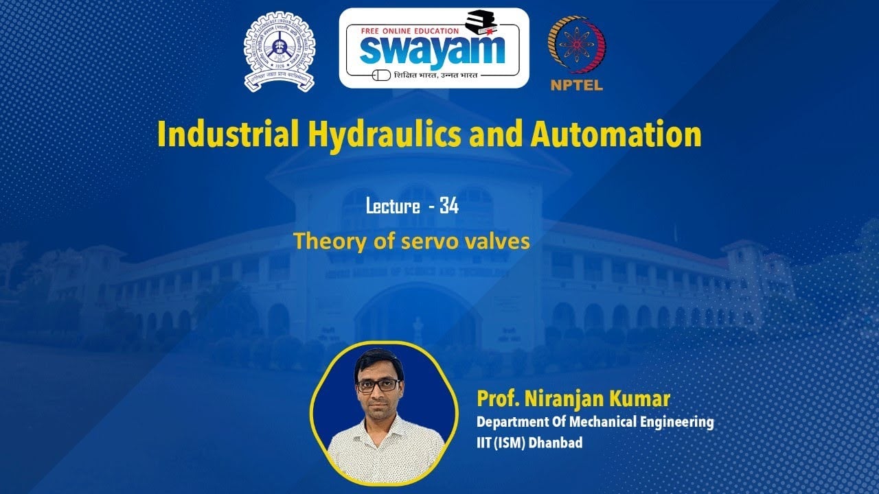
University lesson: proportional and servo valve principles
This NPTEL IIT Kharagpur university lecture explains the general construction and operating principles of proportional and servo valves. Model-specific settings and adjustment permissions still require exact component documentation.
Technical references
- NPTEL: servo and proportional control principles
- NPTEL: proportional solenoids, feedback and dither
- NIOSH: hazardous-energy isolation
These sources provide technical, educational and safety context. Example calculations are illustrative, and neither their inputs nor another manufacturer’s component data establish a Prance product rating or brand affiliation.