Wenzhou Prance Hydraulic Equipment Co., Ltd

Hydraulic Spool Metering Notches: How Geometry Shapes Low-Flow Control
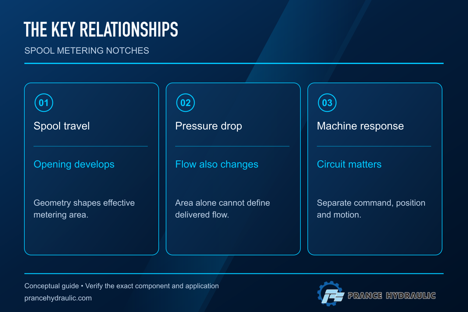
Hydraulic valve spool metering notches shape how the effective flow opening develops as the spool moves. Their purpose is to influence the relationship between displacement, opening area and delivered flow, particularly near small openings. Notch shape alone does not determine actuator speed: pressure drop, fluid properties, valve electronics and the rest of the circuit also matter. Separate this area-development question from spool overlap, which concerns the neutral relationship between lands and ports. For selection, request the approved spool code and flow-characteristic data under stated conditions rather than choosing a valve from the appearance of a groove.
What a metering notch changes
A spool valve meters fluid where relative movement opens a passage between connected galleries. A notch modifies the geometry at that metering region, allowing the available opening to develop differently from a simple straight edge. This can support more useful control over part of the travel, but the result depends on the complete design.
Think of the notch as part of an area schedule: the relationship between spool travel and opening area. A small initial increase in area can make low-flow adjustment less abrupt, while a larger increase later can provide greater capacity. That description explains a design objective, not a guaranteed characteristic of every notched spool. Actual behavior must come from the relevant data or measurement.
O University of Minnesota research treats the relationship between spool position and metering area as a design problem. The Journal of Mechanical Engineering source also models specially designed metering edges. These sources support investigating geometry and flow together; neither identifies the hidden notch dimensions inside a Prance catalog valve.
Keep notch geometry separate from overlap and deadband
Spool overlap describes the relationship of lands and ports around a reference position. Positive overlap can delay the beginning of an opening, while the notch then influences how the opening develops after metering starts. The two features interact, but they answer different questions. One concerns where flow begins; the other concerns how the area evolves with further travel.
Electrical deadband introduces another distinction. A command may change without enough force or spool movement to create a useful hydraulic response. Friction, electronics, compensation settings and the hydraulic load can contribute. A command-to-flow graph therefore combines more than notch geometry. Without actual spool-position measurement, it is easy to attribute the whole response to the wrong feature.
This matters during troubleshooting. A delay before any movement could involve neutral overlap, signal conditioning or load pressure. A steep speed change after movement begins may involve local flow gain, available pressure or the operating point. Replacing a spool because the machine feels abrupt skips the evidence needed to distinguish these possibilities.
Use the orifice relationship with clear limits
A simplified turbulent-orifice relationship is Q = Cd × A × √(2Δp / ρ). Here Q is volume flow, Cd is discharge coefficient, A is effective opening area, Δp is the pressure drop across the metering region and ρ is fluid density. Use consistent units: cubic metres per second, square metres, pascals and kilograms per cubic metre.
This relationship explains why area alone is insufficient. At the same effective area, a different pressure drop changes flow. Under the simplified assumptions and a constant coefficient, quadrupling pressure drop doubles flow. That ratio is an educational consequence of the equation, not a prediction for every operating point of a real proportional valve.
At small openings, viscosity, clearances, edge shape and changing flow conditions can affect the coefficient and the validity of a simple model. Cavitation and flow forces can add further complications. Avoid deriving an exact product curve by inserting an assumed area into the equation. A calculation is most useful when its assumptions are explicit and its result is compared with approved test data.
Compare area, flow and machine response
| Relationship | What it describes | O que não estabelece |
|---|---|---|
| Spool travel versus opening area | Geometric development of the metering passage | Flow at every pressure drop |
| Spool travel versus measured flow | Hydraulic response under the stated test conditions | Response under a different load or fluid condition |
| Electrical command versus spool position | Electronics, actuation and mechanical response | Available actuator flow by itself |
| Electrical command versus flow | Combined electrohydraulic behavior | Notch geometry in isolation |
| Command versus actuator speed | Valve, actuator and circuit response together | A valve-only characteristic |
A useful supplier graph states which of these relationships it represents. It also identifies pressure conditions, fluid temperature or viscosity, spool code and test direction. Without that context, curves from two valves may appear comparable while describing different measurements. A percentage command axis should not be relabelled as millimetres of spool travel unless the mapping is documented.
Understand low-flow gain without assuming a universal shape
Flow gain describes how much flow changes for a change in an input around an operating point. Specify whether that input is command or spool travel. For the simplified relationship at fixed pressure drop, local gain depends on how rapidly area changes with displacement, as well as on the discharge behavior. This is why the area schedule matters.
Geometrical labels such as triangular or rectangular are incomplete descriptions. Depth, width, number, distribution and interaction with the surrounding sleeve or body all affect the actual passage. A two-dimensional sketch does not capture every three-dimensional restriction. Nor does a familiar shape prove that the result will be linear over the full stroke.
Use geometry samples in this article as conceptual comparisons only. They are not manufacturing drawings, measured sections or reconstructions of a 4WRAE valve. No dimensions or machining instructions are provided. Altering a spool can change metering, leakage, strength and load behavior; it should not be treated as a routine field adjustment.
Why a larger valve can make gentle control harder
A valve chosen mainly for maximum flow can place normal operation close to its small-opening region. If a small command change produces a large flow change there, the operator or controller may struggle to achieve gentle motion. This is a system-selection concern, not proof that the valve is faulty or its notch is poorly designed.
Compare the application’s minimum useful flow with its maximum required flow. Include the pressure drop available at each condition. A valve’s nominal flow rating usually belongs to specified test conditions, so do not assume that the same flow appears at every load. Also check whether supply pressure changes as other functions operate.
Before selecting a different spool, examine command scaling, actuator size, supply behavior and the required motion range. A change intended to improve low-flow control can restrict maximum speed or increase throttling losses. The engineering decision should balance those requirements using the approved characteristics and an application review.
Measure a repeatable response before diagnosing geometry
Use an approved test plan with the machine safely configured. Record command, available spool-position feedback, supply and work-port pressures, flow or actuator speed, and oil condition. State which measurements are direct and which are inferred. Do not describe a command signal as actual spool position when no position sensor is present.
Compare repeated tests at the same conditions. If an apparent gain change follows temperature or load, the pressure-flow relationship may explain part of it. If rising and falling commands produce different outputs, examine hysteresis separately from the average metering slope. Oscillation can involve controller tuning, mechanical compliance or pressure dynamics rather than the notch alone.
Preserve raw traces and sensor details. A single photograph of a gauge beside an electrical display cannot establish a full flow characteristic. Where a safe test cannot isolate valve behavior, document that limitation and avoid presenting a machine-level response as a laboratory valve curve. Reliable conclusions depend on knowing what the evidence can actually distinguish.
Specify a valve using the complete spool code
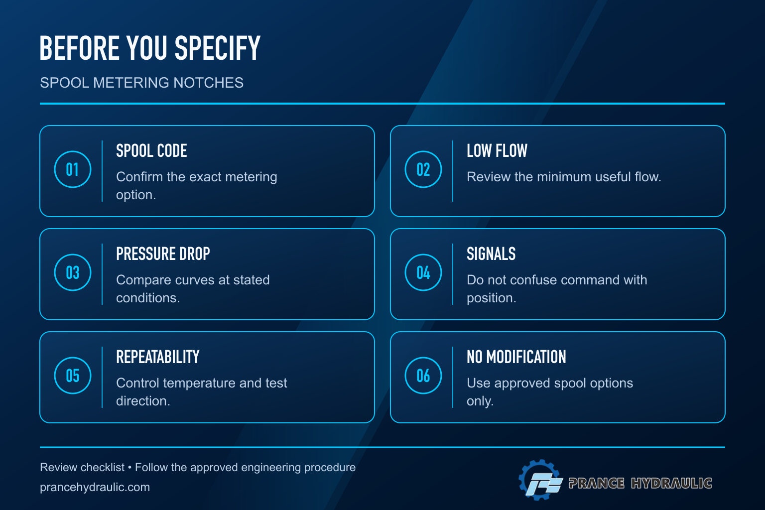
For a Prance 4WRAE inquiry, provide the complete valve and spool code, supply arrangement, required flow range and the motion-control objective. State whether the concern is fine approach, smooth acceleration, reversing behavior or repeatable steady speed. These operating goals are more useful than asking for a good notch shape without application context.
Request flow data for the relevant pressure drop and fluid condition. Confirm the control signal, electrical supply, mounting interface and any required feedback arrangement. Position feedback can improve knowledge of spool motion, but it does not make flow independent of hydraulic conditions. Do not transfer characteristics from a different spool or another valve series merely because the product names look similar.
The catalog product is a business reference for the proportional valve category. Its external photograph does not establish the notch geometry inside the supplied unit. The next selection step is therefore a documented characteristic review, followed by commissioning against the required motion range, rather than a visual judgment about an imagined internal part.
Perguntas frequentes
What is the purpose of a spool metering notch?
It modifies how the effective opening area develops with spool movement. The resulting flow still depends on pressure drop, fluid conditions and the complete valve design.
Is a metering notch the same as spool overlap?
No. Overlap concerns the neutral relationship of lands and ports. A notch influences area development through the metering range, although both features can affect low-command behavior.
Does a triangular notch guarantee linear flow?
No. A shape label does not define the full three-dimensional passage, discharge behavior or pressure conditions. Use approved characteristic data rather than assuming a universal curve.
Can position feedback remove pressure-dependent flow changes?
No. Position feedback provides information about spool motion. Flow through the opening remains dependent on the hydraulic conditions unless the complete system provides suitable compensation.
Should a spool be modified to improve low-speed control?
Do not machine or modify it as a field workaround. First investigate the measured response and review approved spool options, command scaling and circuit conditions with the responsible supplier.
Produtos e recursos de engenharia relacionados
The Proportional Valve 4WRAE is the relevant product category for this guide. The illustrations explain concepts and do not depict the product internals or establish operating limits. Confirm the complete code and approved documentation. Related resources: Válvula Proporcional 4WRAE, Área de válvulas hidráulicas, Sobreposição do Carretel da Válvula Hidráulica: Sobreposições Positiva, Nula e Negativa, Como é que as condições do centro da válvula de distribuição afetam um circuito?.
Sources and limits of this guide
Educational principles and explicitly hypothetical calculations only. No pressure, time limit, internal geometry, thermal-relief setting or performance curve is assigned to a Prance product. Actual service and selection require the approved data sheet for the complete order code and circuit review.
- NPTEL: Industrial Oil Hydraulics and Pneumatics
- NIOSH: hazardous energy prevention
- Journal of Mechanical Engineering: modelling specially designed metering edges
- University of Minnesota: analysis and synthesis of spool metering area
University lesson: operating principles
NPTEL-NOC IITM presents 5.4 – Directional Control Valves. The lesson supports the directional valve operation; no model-specific notch geometry is asserted used in this discussion; it is not a model-specific performance or installation approval.