Wenzhou Prance Hydraulic Equipment Co., Ltd

")
")
")
")
")
")
Fixed Displacement motor A2F
1.High performance rotary pump with well-power spherical control area with the advantage; Self centering low peripheral speed, high efficiency .
2.Drive shaft capable of adopting radial loading .
3.ISO mounting flange, uniform for fixed displacement pumps/motors and variable motors
4.Mybe used in conjunction with fire-resistance fluids.
5.Low nosie generation.
Detailed description
This is a high-performance rotary pump equipped with a well-powered spherical control area, which brings three key advantages: self-centering, low peripheral speed, and high efficiency. The self-centering design ensures stable operation of the pump, avoiding deviation or wear caused by misalignment during operation; the low peripheral speed effectively reduces mechanical friction and noise, while extending the service life of internal components; the high efficiency feature minimizes energy loss, enabling the pump to convert more input power into effective hydraulic output. Its drive shaft is specially designed to be capable of adopting radial loading, which means it can bear radial forces during operation without damage or performance degradation, enhancing the pump’s adaptability to complex working conditions. It is equipped with an ISO mounting flange, which is uniform for fixed displacement pumps/motors and variable motors, ensuring good interchangeability and compatibility, facilitating installation, maintenance, and system upgrades. The pump can be used in conjunction with fire-resistance fluids, making it suitable for scenarios with high fire safety requirements, such as industrial sites with flammable and explosive risks. Additionally, it features low noise generation, thanks to its optimized structural design and low peripheral speed, creating a quieter working environment and reducing noise pollution in the operation site.
Technical Data
Inlet Operating Pressure:
Pump :
Minimum pressure at ports S, A or B: Pabs------------------0. 08MPa In closed circuits, the feed
pressure must be between 0.2MPa and 0.6MPa, depending on pump speed and viscosity of hydraulic fluid.
•Motor: Pressure at port A or B:
Nominal pressure--------------------Pn =35MPa
Peak pressure---------------------Pmax=40MPa
The sum of the pressures at ports A and B must not exceed 7OMPa
(individual pressure on either side max 40MPa)
•outlet Operating Pressure
•Pump: Nominal pressure--------------Pn=35MPa
Peak pressure--------------Pmax=40MPa
Maximum permissible case pressure(at port T):
Pabs---------------0.2MPa
•Oil Temperature Range:-25℃~80℃
•Viscosity Range
T min------------------------------------------10mm2/s
T max----------------( for short periods ) 1000mm2/s
Optimum Operating Viscosity:---------------------------16-25mm2/s
Fluid Recommendation :40 low-solidifing
•Filtration of hydraulic Fluid:
Recommended filtration 10um. Coarser filtration of 25 to40um is acceptable,However longer service life is achieved.
•Speed Range:
No limitation on minimum speed,
If high uniformity of rotation is required,nmin should not be less than 50r/min,See table on page 5 for maximum speed.
•Mounting position:
Arbitrarily Choose, the housing must be filled with oil;
•Flow direction:
| Clockwise: | Anticlockwise: |
| A to B S toB(Open Circuit) | B to A S to A(Open Circuit) |
Rear cover:
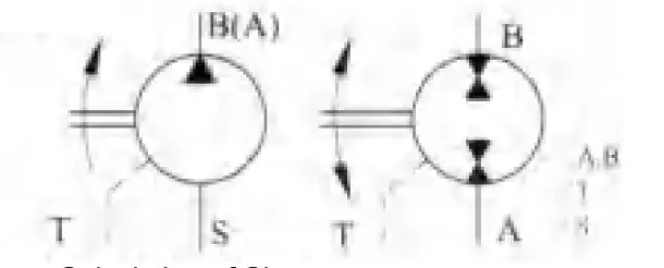 |
PresssurePort Drain Port Suction |
||
| Calculation of Size | |||
| pump: | Output Flow | Q=(Vg×n×ŋv)/1000 | [L/min] |
| Intput Torque | M=0.159×Vg×Δp/ŋmh | [N:m] | |
| Intput power | P=(Q×Δp)/(60×ŋt) | [Kw] | |
| Motor: | Input Flow | Q=(Vg×n)/(1000×ŋv) | [L/min] |
| Output Speed | n=(Q×1000×ŋv)/Vg | [r/min] | |
| Output Torque | M=0.159×Vg×Δp×ŋmh | [Nm] | |
| Output power | P=(Q×Δp×ŋt)/60 | [Kw] | |
| Vg=max geometric displacement | [ml/r] | ||
| M=torque | [N.m] | ||
| Δp=differential pressure | [Mpa] | ||
| n=speed | [r/min] | ||
| ηv=volumetric efficiency | |||
| ηm=mechanical- -hydraulic efficiency | |||
| ηt=overall efficiency | |||
| Used for close system pump. /motor |
system | 10~160 | 200~500 | ||
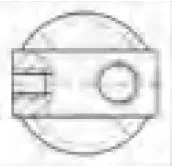
| 1.A,B Thread |
 |
6.A,B Flange |
 |
1. A,B Flange | |
| 2. A,B Flange |
 |
7.A,B Flange |
 |
 |
|
| Used for open system punp |
3.A,B Flange |
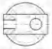 |
5.B,S Prick Worm |
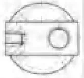 |
2.B,S Flange |
| 4.B,S Thread |
 |
 |
|||
Technical Data Theoretical Values, Without Considering η m and ηV, Values rounded Off.
| Size | 10 | 12 | 23 | 28 | 45 | 55 | 63 | 80 | 107 | 125 | 160 | 200 | 250 | 355 | 500 | ||
| Displacement Vg(ml/r) | 9.4 | 11.6 | 22.7 | 28.1 | 44.3 | 54.8 | 63 | 80 | 107 | 125 | 160 | 200 | 250 | 355 | 500 | ||
| Max Speed n max(r/min) |
Close Circuit | 7500 | 6000 | 5600 | 4750 | 4500 | 3750 | 4000 | 3350 | 3000 | 3150 | 2650 | 2500 | 2500 | 2240 | 2000 | |
| Open Circuit Inlet Pressure (Pabs=MPa) |
0.09 | 4700 | 3750 | 3750 | 2800 | 2850 | 2360 | 2550 | 2120 | 1900 | 2120 | 1650 | 1700 | 1400 | 1250 | 1120 | |
| 0.10 | 5000 | 4000 | 4000 | 3000 | 3000 | 2500 | 2700 | 2240 | 2000 | 2240 | 1750 | 1800 | 1500 | 1320 | 1200 | ||
| 0.15 | 6000 | 4900 | 4900 | 3600 | 3550 | 3000 | 3300 | 2750 | 2450 | 2750 | 2100 | 2180 | 1850 | 1650 | 1500 | ||
| Max Flow Q max(I/min) |
Close Circuit | 71 | 70 | 127 | 133 | 199 | 206 | 253 | 268 | 321 | 394 | 424 | 500 | 625 | 795 | 1000 | |
| Open Circuit Inlet Pressure (Pabs=MPa) |
0.09 | 43 | 42 | 83 | 76 | 122 | 125 | 156 | 165 | 197 | 257 | 256 | 330 | 340 | 430 | 543 | |
| 0.10 | 46 | 45 | 88 | 82 | 129 | 133 | 165 | 174 | 208 | 272 | 272 | 349 | 364 | 455 | 582 | ||
| 0.15 | 55 | 55 | 108 | 98 | 157 | 159 | 202 | 213 | 251 | 333 | 326 | 423 | 449 | 568 | 728 | ||
| Max Power Pmax(Kw) Δp=35MPa |
Close Circuit | 41 | 41 | 74 | 78 | 116 | 120 | 147 | 156 | 187 | 230 | 247 | 292 | 365 | 454 | 583 | |
| Open Circuit Inlet Pressure (Pabs =MPa) |
0.09 | 25 | 25 | 48 | 44 | 71 | 73 | 91 | 96 | 115 | 150 | 149 | 192 | 198 | 251 | 317 | |
| 0.10 | 27 | 26 | 51 | 48 | 75 | 78 | 96 | 101 | 121 | 159 | 159 | 204 | 212 | 265 | 340 | ||
| 0.15 | 32 | 32 | 63 | 57 | 92 | 93 | 118 | 124 | 148 | 194 | 190 | 247 | 262 | 331 | 424 | ||
| Electric Motor Speed n=1450/min |
Flow Close Circuit |
13.6 | 16.8 | 32.9 | 40.7 | 64.2 | 79.5 | 91.3 | 116 | 155.2 | 181.2 | 232 | 290 | 363 | 515 | 725 | |
| Q(l/min)Open Circuit |
13.2 | 16.3 | 31.9 | 39.5 | 62.3 | 77.1 | 88.6 | 112.5 | 150.5 | 175.8 | 225 | 281 | 352 | 499 | 703 | ||
| P(Kw) Close Δp=35MPa Open |
7.9 | 9.8 | 19.2 | 23.7 | 27.4 | 46 | 53 | 67.7 | 90 | 106 | 135 | 169 | 212 | 300 | 423 | ||
| 7.7 | 9.5 | 18.6 | 23 | 36.3 | 45 | 51.7 | 66 | 88 | 1.3 | 131 | 169 | 212 | 300 | 423 | |||
| Torque(N.m) | Δp= 10MPa | 15 | 18 | 36 | 44.7 | 70 | 87 | 100 | 127 | 170 | 199 | 254 | 318 | 398 | 564 | 795 | |
| Δp=35MPa | 52 | 65 | 126 | 156 | 247 | 305 | 351 | 445 | 595 | 696 | 890 | 1113 | 1391 | 1976 | 2783 | ||
| Approx Weight (kg) | 5 | 5 | 12 | 12 | 23 | 23 | 33 | 33 | 44 | 63 | 63 | 88 | 88 | 138 | 185 | ||
Notes:
1.These values are valid provided there is an absolute pressure at suction inlet Sand when operated on mineral oil.
Permissible speed nperm can be determined from the nomograph. In motor operation the permissible speed for closed circuit system and boosted operation are also valid for open circuit system. When suction pressure Pabs > 0. 1MPa, the permissible speed can be increased in open circuits (Self-suction operation). But when suction pressure Pabs < 0.1 MPa, the permissible speed must be reduced.
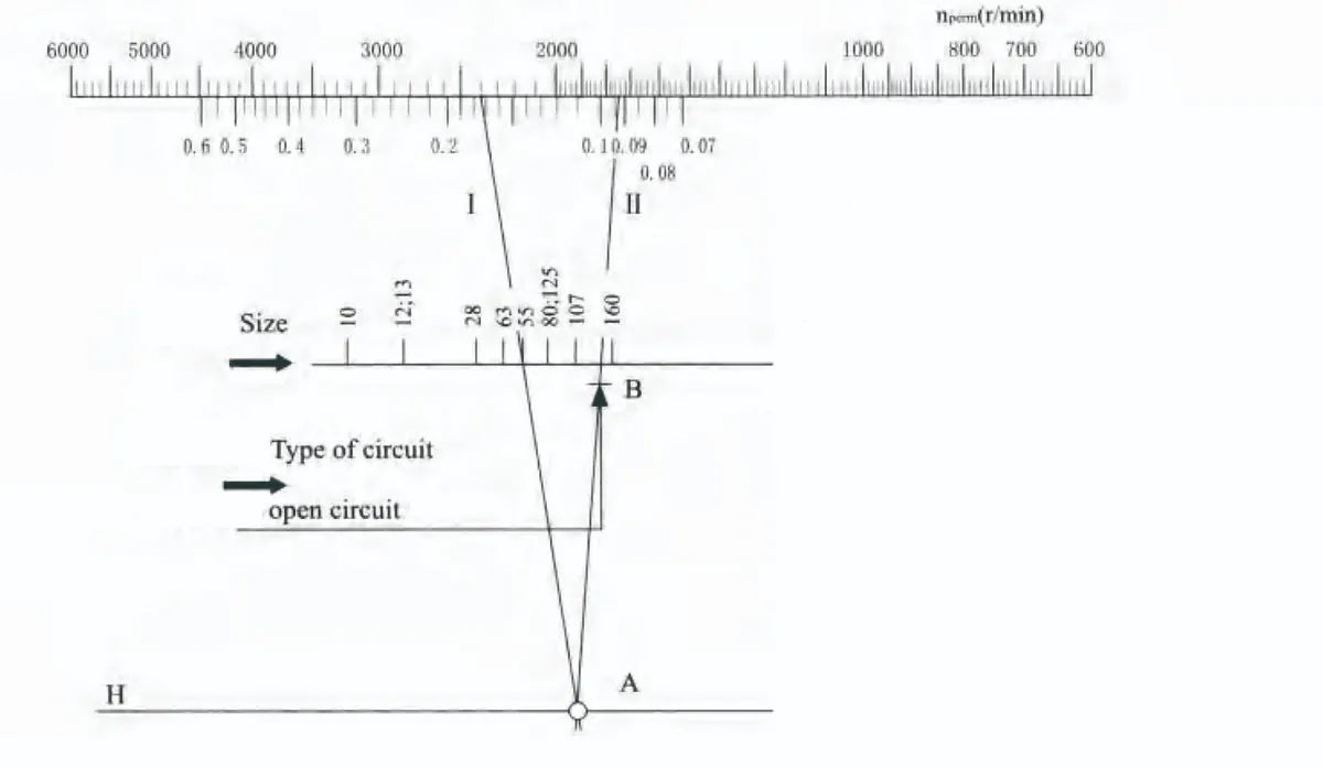
Example:
Given:size 55,Drive speed 2400r/min
Required:pressure Pabs at the suction Inlet S.
Solution:Line 1 on scale nperm drawn towards size 55 crosses line H at point A .line 11 from point A to point B(open circuit) gives the result:
Pabs > 0.094MPa.
The following are always used together:
1.Scales Pabs,type of circuit and line H.
2.Line H,size scale and nperm.