Wenzhou Prance Hydraulic Equipment Co., Ltd

")
")
")
")
")
")
Axial Piston Fixed Pump A17FO Series 10
1.Bent Axis Design;
2.Optimized for Mobile Drives;
3.Compact and Lightweight Construction;
4.Direct Power Take-Off Installation;
5.Excellent Suction Characteristics;
6.High Overall Efficiency
Detailed description
This product adopts a reliable bent axis design with a rational structural layout, delivering stable and adaptive performance for diverse operating conditions. Optimized exclusively for mobile drive systems, it perfectly accommodates dynamic load changes and complex working scenarios of mobile machinery and vehicle-mounted equipment. Featuring a compact and lightweight construction, it eliminates redundant structural designs, effectively saving installation space and reducing overall equipment load while maintaining structural durability. It supports direct power take-off installation without complicated adapter parts, simplifying assembly procedures and cutting down installation time and costs. Equipped with excellent suction characteristics, the device ensures smooth and stable suction operation, effectively avoiding cavitation and flow interruption during operation to adapt to various medium transmission conditions. With optimized internal transmission and structural design, it achieves high overall efficiency, minimizing energy loss and delivering consistent, long-term operational stability for improved working performance and cost-effectiveness.
Selection and RFQ
This product series should be selected against the approved hydraulic circuit. Confirm required flow or displacement, continuous and peak pressure, drive speed, control arrangement, fluid and installation interface before final selection.
Information to include in your RFQ
- Required displacement or flow at operating speed
- Continuous and peak system pressure
- Drive speed, control requirement and circuit type
- Mounting flange, shaft, ports, fluid and filtration requirement
Related resources
Technical Data
| Size | NG | 23 | 32 | 45 | 63 | 80 | 107 | ||
| Displacement, geometric, per revolution | Vg | cm3 | 22.9 | 32 | 45.6 | 63 | 80.4 | 106.7 | |
| Speed maximum1) | nnom2) | rpm | 3050 | 2750 | 2650 | 2200 | 2150 | 2000 | |
| nmax3) | rpm | 4300 | 3900 | 3800 | 3200 | 3100 | 2800 | ||
| Flow | at nnom | qv | l/min | 70 | 88 | 121 | 139 | 173 | 213 |
| Power | at nnom and Δp= 350 bar | P | kW | 41 | 51 | 71 | 81 | 101 | 124 |
| Torque | at Δp = 350 bar | T | Nm | 127 | 178 | 254 | 351 | 448 | 594 |
| Rotary stiffness | C | kNm/rad | 2.56 | 3.12 | 4.18 | 6.25 | 8.73 | 11.2 | |
| Moment of inertia for rotary group | JTW | kgm2 | 0.0012 | 0.0012 | 0.003 | 0.0042 | 0.0072 | 0.0116 | |
| Maximum angular acceleration | α | rad/s2 | 6500 | 6500 | 14600 | 7500 | 6000 | 4500 | |
| Case volume | V | l | 0.25 | 0.29 | 0.4 | 0.5 | 0.6 | 0.75 | |
| Mass moment | TG | Nm | 4.7 | 4.7 | 8.6 | 9.9 | 15.3 | 20 | |
| Mass (approx.) | m | kg | 5.9 | 5.9 | 8.4 | 9.3 | 12.3 | 15.0 | |
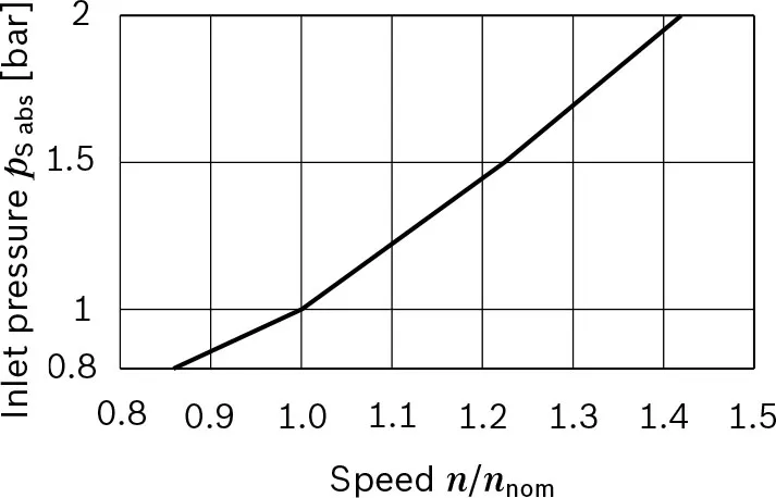
▼Maximum speed (limiting speed)
Determining the operating characteristics
| Flow | qv=(Vg×n×ηv)/1000 | [l/min] |
| Torque | T=(Vg×Δp)/(20×π×ηhm) | [Nm] |
| Power | P=(2π×T×n)/60000=(qv×Δp)/(600×ηt) | [kW] |
Key
Vg=Displacement per revolution [cm3]
Δp=Differential pressure [bar]
n=Speed [rpm]
ηv=Volumetric efficiency
ηhm=Hydraulic-mechanical efficiency
ηt=Total efficiency ( ηt=ηv × ηhm)
Note
▶Theoretical values, without efficiency and tolerances;values rounded.
▶Operation above the maximum values or below the minimum values may result in a loss of function,a reduced service life or in the destruction of the axial piston unit. Other permissible limit values, such as speed variation, reduced angular acceleration as a function of the frequency and the permissible angular acceleration at start (lower than the maximum angular acceleration) can be found in data sheet 90261.
1) The values are applicable:
- for the optimum viscosity range from νopt = 36 bis 16 mm2/s
- for hydraulic fluids based on mineral oils.
2) The values apply at absolute pabs =1 bar at suction port S
3) Maximum speed (speed limit) with increased inlet pressure pabs at suction port S (see diagram).
Permissible axial forces of the drive shaft
| Size | NG | 23 | 32 | 45 | 63 | 80 | 107 | ||
| Maximum axial force, at standstill or pressure-free operation | 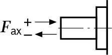 |
+Fax max | N | 0 | 0 | 0 | 0 | 0 | 0 |
| -Fax max | N | 24 | 33 | 43 | 53 | 60 | 71 | ||
Note
▶The values given are maximum values and do not apply
to continuous operation.
▶The permissible axial force in direction -Fax is to be avoided as the lifetime of the bearing is reduced.
▶Radial forces are not permissible.
