Wenzhou Prance Hydraulic Equipment Co., Ltd

Hydraulic System Water Contamination: Detection and Removal
Hydraulic system water contamination should be confirmed with a representative oil sample and a suitable laboratory method before choosing a removal process. Clear oil can contain dissolved water, while cloudy oil can indicate an emulsion, entrained air or another change that requires investigation. Stop the source of ingress, identify the fluid, and obtain a component-specific acceptance limit. Then choose a treatment that is compatible with that fluid and verify the result under comparable conditions. This guide gives maintenance teams and component buyers a practical investigation sequence; it does not assign a universal water limit to every hydraulic pump.
Establish what the machine actually contains
Start with the oil identity rather than its appearance. Record the manufacturer, product name, viscosity grade, batch if available, and any fluid changes. A mineral oil system and a deliberately water-containing fire-resistant fluid need different interpretations. Applying a mineral-oil drying target to a water-glycol system can change the fluid composition in the wrong direction. Ask the fluid supplier to confirm its formulation and permitted water condition before approving treatment.
Collect the pump, motor, valve and seal requirements for the exact installed configuration. The most restrictive documented requirement may determine the system target, but a component family name alone does not establish that requirement. A product photo identifies an exterior; it cannot demonstrate the fluid approval, allowable water concentration or internal material specification. When replacing a damaged pump, include the contamination history in the enquiry so the new component is reviewed against the actual operating environment.
Separate dissolved, emulsified and free water
Dissolved water is mixed at a molecular level and may leave oil looking clear. Its concentration relative to the oil's saturation capacity changes with fluid chemistry and temperature. A sample that is clear while warm may behave differently after cooling. Record both the operating condition and the sample condition; do not treat a visual change during storage as a precise measurement of the operating circuit.
Emulsified water is dispersed as droplets. Free water is a separate phase that can settle or collect at low points. A jar observation can suggest which condition needs investigation, but it cannot establish a representative system concentration. Settled water in a drain sample and circulating oil from a live sampling location answer different questions. Preserve both results with their sampling locations instead of averaging them into one reassuring number.
Build a sampling record that supports a decision
Use an approved sampling point and the site's safe sampling procedure. A running pressurized line needs equipment and training suited to its pressure and temperature. Never loosen a fitting to obtain a convenient sample. If the system must be opened, isolate energy, secure suspended loads and release stored pressure using the machine procedure. Accumulators and trapped sections can retain energy after the drive has stopped.
Specify a clean, dry container appropriate to the laboratory's instructions. Moisture introduced by a bottle or cap can make a low-level measurement misleading. Identify the date, time, operator, sample point, operating load, oil temperature and time since the last fill or maintenance activity. Keep the cap closed and protect the sample during transport. Ask the laboratory how much oil it needs and whether a second bottle is required for particle counting or other tests.
Repeat samples should come from the same point under comparable conditions. A post-treatment sample taken from a temporary processing outlet should not be silently compared with a pre-treatment sample from the reservoir bottom. If the location changes, state the change explicitly and explain what the new result demonstrates.
Choose a measurement method and interpret its limits
ASTM D6304 describes coulometric Karl Fischer water determination for petroleum products and lubricating oils, including direct and indirect approaches. Its public scope identifies potential interferences. Ask the laboratory which procedure it used, whether it is suitable for this fluid, and how it handled the sample. The standard's measurement scope does not supply a hydraulic-component acceptance limit.
Request the units, detection capability and uncertainty that apply to the reported result. A mass concentration in mg/kg is numerically equivalent to parts per million by mass. A saturation reading expressed as a percentage is a different quantity: it describes proximity to the water saturation condition for that oil and temperature. Do not convert between the two without a fluid-specific relationship. A sensor trend can help locate an event even when a laboratory result is still needed for release.
A negative or unchanged particle-count result does not prove that the oil is dry. Particle cleanliness and water condition are separate checks. Water droplets can also complicate some optical counting conditions, so tell the laboratory if an emulsion is suspected. Ask for an interpretation appropriate to the sample rather than treating every reported channel as an independent solid-particle result.
Trace the entry route before ordering treatment
Create a timeline of the first abnormal observation and the events before it. Check fills, drum storage, container handling, washing, rain exposure, seal work, cooler service and overnight cooling. Inspect the reservoir closure, breather arrangement and accessible exterior interfaces using the approved maintenance procedure. The objective is to find a plausible route and then obtain evidence for it; a damp environment alone does not prove where the water entered.
For a water-cooled oil cooler, include a qualified leakage assessment when the machine design makes cross-contamination possible. Pressure relationships vary during operation and shutdown. Avoid concluding that one pressure reading rules out every leak condition. If contamination appears after cleaning, compare the washing method and protection of openings with the timing of the sample changes. Correct the route before restarting normal service, otherwise treatment becomes a repeated expense.
Compare removal options against the fluid and contamination state
| Option | What to verify before use | What the result cannot prove by itself |
|---|---|---|
| Controlled drainage of separated water | A safe drain arrangement and confirmation of a separate phase | Removal of dissolved water elsewhere in the circuit |
| Water-absorbing filtration | Element compatibility, rated capacity and replacement criteria | Unlimited capacity or suitability for an intentionally water-based fluid |
| Coalescing treatment | Fluid properties and the equipment's documented separation capability | Effective separation of every stable emulsion |
| Vacuum dehydration | Approved fluid, temperature limits, process controls and vendor evidence | A component water limit or repair of a continuing ingress route |
| Fluid replacement | Fluid approval, waste handling and residual-oil management | Removal of water trapped in every branch or correction of the original leak |
Supporting technical context: ASTM D6304: water determination method scope, NPTEL: industrial hydraulic fluids and accessories. This evidence checklist does not establish a product rating or universal acceptance limit.
This decision table is qualitative. Obtain the treatment provider's written operating limits and demonstrate suitability with the actual fluid. A conventional particulate filter should not be assumed to remove dissolved water simply because it produces a better particle count. Likewise, a treatment unit's nominal throughput is not a promise that the entire machine inventory reaches the target after one pass.
For severe contamination, the equipment owner may need to assess the oil's wider condition before investing in drying it. Removing water does not reverse every chemical change or mechanical damage that occurred. Compare treatment and replacement using laboratory interpretation, downtime, residual contamination and the machine's release requirements. Do not add an unapproved additive merely to improve the appearance of the sample.
Protect the pump during the recovery decision
Keep suction and case-drain arrangements within their documented conditions while any temporary processing equipment is connected. An extra connection, closed valve or poorly planned return can create a different fault. The treatment circuit requires its own reviewed drawing, permitted flow and isolation plan. This guide does not specify temporary plumbing or authorize operation outside component limits.
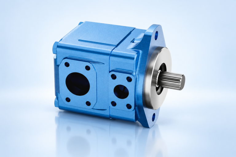
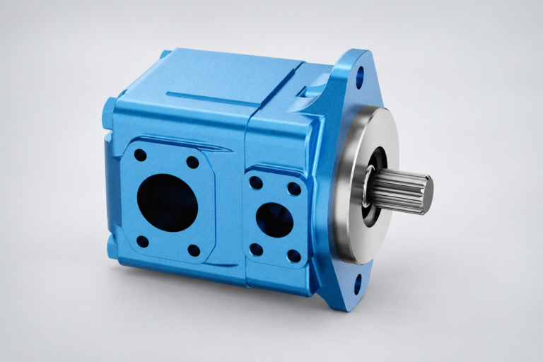
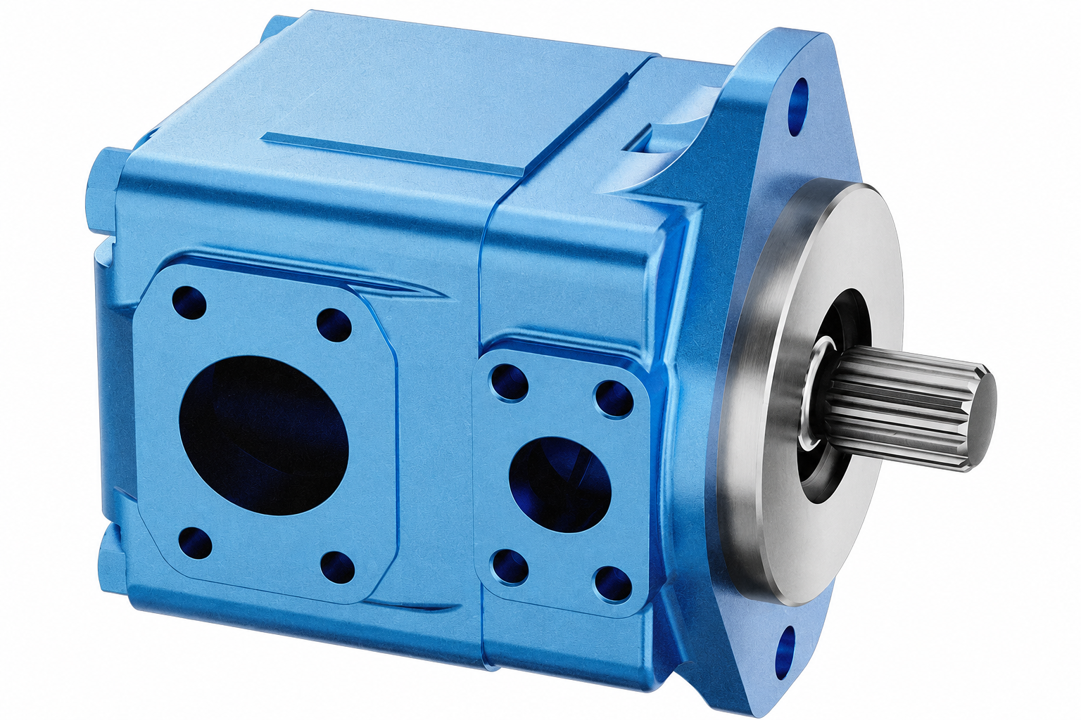
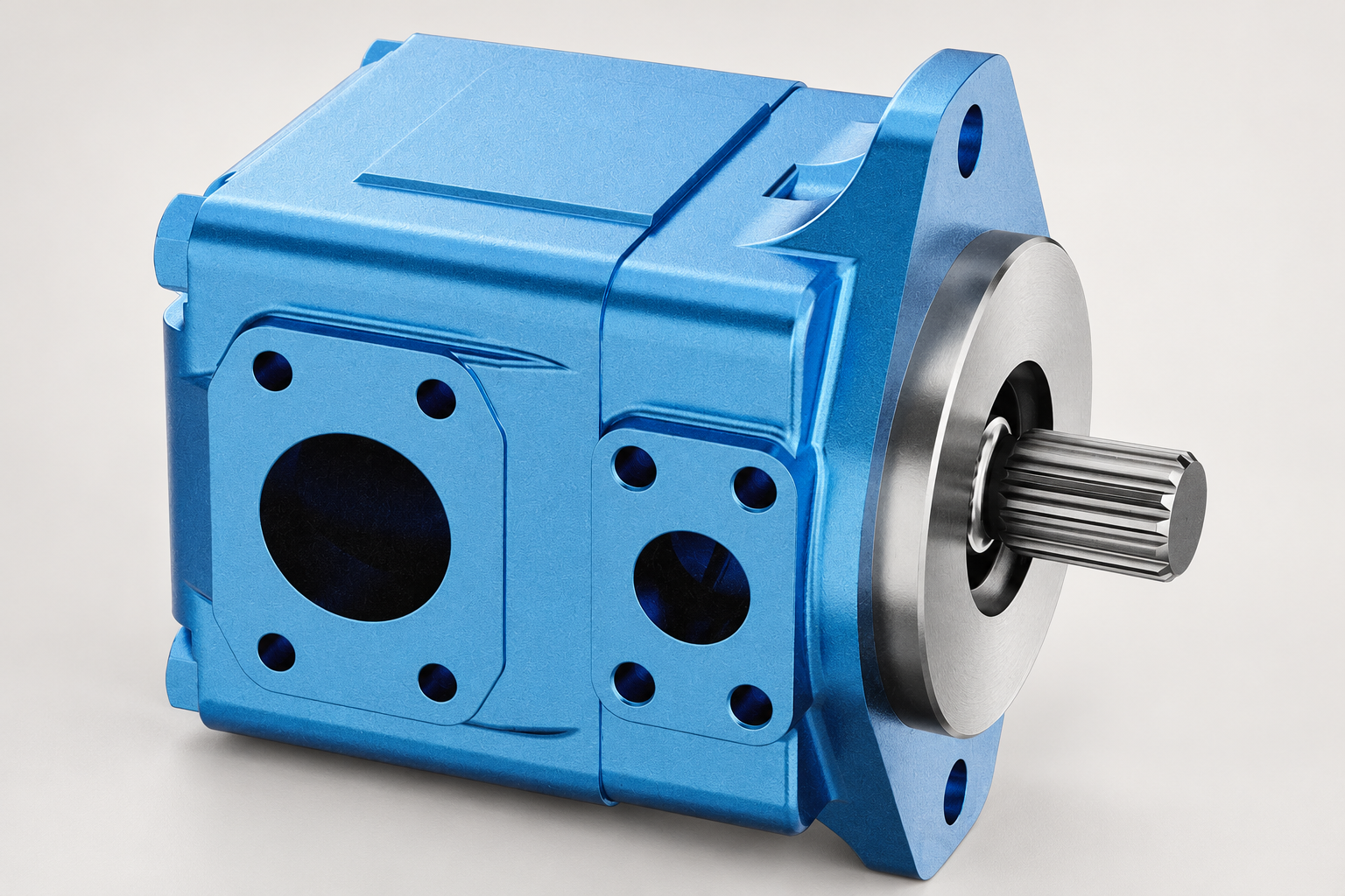
Where noise, abnormal drain flow, pressure instability or overheating accompanies water findings, retain those observations as separate evidence. They may justify component inspection, but none identifies water as the only cause. Photograph accessible interfaces after safe isolation and record the fault sequence. Preserve the removed component if the supplier or laboratory needs to examine it. An exterior image of a T6 vane pump supports identification of the housing and connections; it is not evidence of measured internal corrosion.
Verify recovery with comparable samples
Define the release conditions before treatment starts. The target should state the fluid, method, units, sample location, acceptable condition and any required stability period. Agree how the machine will be circulated or operated for a representative check without exceeding limits. A very low result at the dehydration outlet can coexist with contaminated residual oil in the machine; the system sample is therefore part of the release decision.
Take the agreed post-treatment samples and compare them with the baseline. If results rebound, investigate remaining inventory and renewed ingress rather than declaring the first result wrong. Record the time between treatment and sampling, temperature, operating duty and any makeup oil. Keep the laboratory reports and treatment record together so another engineer can understand the sequence without relying on memory.
Give the supplier a useful enquiry package
For a replacement pump or valve enquiry, provide the exact component identification, fluid data sheet, water results, test method, particle data if available, operating temperatures and a short fault timeline. Include the approved circuit drawing and any treatment connection proposed. Ask for documented fluid compatibility and the relevant component requirements, plus inspection or return-to-service recommendations for the observed condition.
For a treatment enquiry, state the approximate oil inventory and the known contamination condition while identifying which values are estimates. Ask how the provider verifies drying effectiveness, avoids overheating the oil and manages consumables. Compare quotations on the same release criteria. A low daily rental cost is not necessarily a low total recovery cost when sampling, mobilisation, incomplete treatment and repeated ingress are excluded.
Keep the topic boundaries clear
This investigation focuses on water identification, its entry route and treatment verification. General pump contamination control covers handling and particulate prevention; an ISO cleanliness guide interprets particle codes; a foaming investigation separates surface foam from entrained air. Use those complementary checks when the evidence calls for them, but retain separate targets and results. This makes the maintenance record more useful and avoids treating one clean-looking sample as proof that every fluid problem has been solved.
Frequently asked questions
Is milky hydraulic oil always water contamination?
Milky appearance is a reason to investigate, not a complete diagnosis. Water droplets, entrained air and fluid changes can affect appearance. Identify the oil and obtain a suitable laboratory result before selecting treatment.
Can a standard hydraulic filter remove all water?
A particulate filter should not be assumed to remove dissolved water. Water-absorbing elements and separation or drying equipment need documented compatibility and capacity for the actual fluid and contamination state.
What water concentration is acceptable for a hydraulic pump?
Use the exact pump, fluid and system requirements. There is no universal acceptance number in this guide. Specify the laboratory method, units, sampling location and operating condition with the target.
Is a saturation percentage the same as ppm water?
No. Saturation percentage relates to the water capacity of that fluid at its temperature. Ppm by mass reports a concentration. Converting between them requires a valid relationship for the particular oil.
Should a new pump be installed immediately after drying the oil?
Release the machine using agreed system samples and the component supplier's instructions. Drying the oil alone does not prove that ingress has stopped or that other contamination and damaged components have been addressed.
Related products and engineering guides
T6 vane pump, vane pump range, pump contamination control, case-drain flow measurement. Provide the circuit, fluid, duty and exact ordered configuration when requesting component-specific data.
University lesson: mod-40 lec-42 AppendicesTutorial on Basic Calculation on HST System and Hydraulic Fluids
This NPTEL university lecture explains hydraulic fluid identity and properties as background for selecting an appropriate fluid-condition investigation. It is not a demonstration of water sampling or dehydration..

Technical references
- ASTM D6304: water determination method scope
- NPTEL: industrial hydraulic fluids and accessories
- NIOSH: hazardous-energy isolation
Sources support the stated principles and method scope. Illustrative inputs and another manufacturer’s documents do not establish Prance component ratings, warranties or brand affiliation.