Wenzhou Prance Hydraulic Equipment Co., Ltd

Hydraulic Oil Foaming: Causes, Tests, and Corrective Actions
Hydraulic oil foaming can result from air entering the system, turbulent return flow, an unsuitable fluid mixture, contamination or degraded foam-control behavior. Persistent surface foam, cloudy oil and a noisy pump are observations, not proof of one common cause. First distinguish surface foam from entrained air, water and vapor cavitation, then inspect the circuit and obtain appropriate fluid evidence. This guide gives maintenance and purchasing teams a practical diagnostic sequence, explains the difference between foam and air-release tests, and shows what to verify before replacing a pump or adding a chemical treatment.
Describe the observation before choosing a remedy
Record where bubbles appear, how long they persist and which machine functions produce them. Note whether the condition occurs during startup, after warm operation, after an oil change or only during a particular movement. Include oil temperature, fluid identity, reservoir level and recent maintenance. A consistent record is more useful than the statement that the machine is foaming badly.
Surface foam is a population of bubbles at the liquid surface. Entrained air is dispersed within the fluid, while dissolved air is present without necessarily being visible as bubbles. These conditions can coexist, but they are not interchangeable laboratory measurements. A machine may show limited surface foam while circulating aerated fluid through the pump.
Cloudiness also needs investigation. Water can alter appearance, and visual inspection alone cannot establish its concentration or whether bubbles explain the observation. Preserve a representative sample and ask the laboratory for the tests relevant to the fluid and suspected condition. Do not label every milky sample as water or every cloudy sample as harmless aeration.
Separate aeration from vapor cavitation
Aeration concerns air entering or becoming dispersed in the fluid. Vapor cavitation involves vapor formation when local pressure falls sufficiently low, followed by bubble collapse as conditions change. Both can produce noise and impaired operation, and a machine can have more than one problem at the same time.
A pump sound recording does not provide a complete diagnosis. Review permitted inlet conditions, fluid viscosity at the actual temperature, inlet restrictions and the maintenance history. Air ingress on a suction-side connection can be possible without an obvious outward oil leak. Conversely, a restricted inlet does not prove that every visible reservoir bubble originated from vapor cavitation.
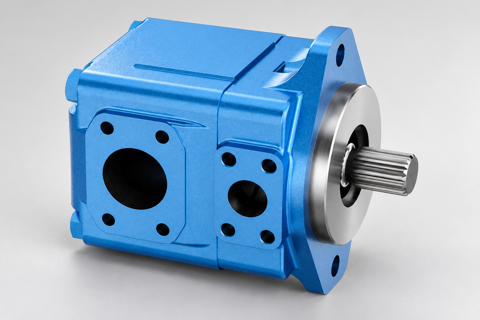
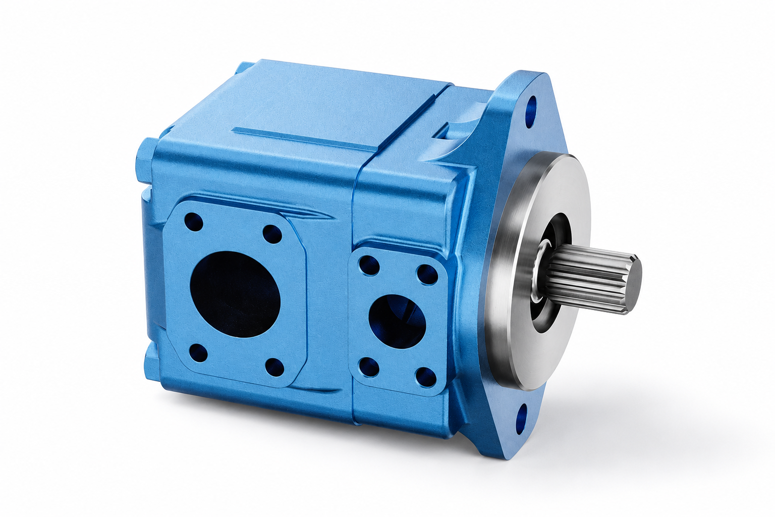
Confirm the selected pump's inlet requirements and the system's approved diagnostic method. Do not apply a generic pressure or vacuum limit to every pump family. An exterior T6 vane-pump illustration can help identify the housing and connections, but it cannot demonstrate the internal condition, inlet margin or allowable viscosity of a particular ordered unit.
Inspect reservoir level and return-flow behavior safely
Check the fluid level using the machine's specified position and procedure. Actuator movement can transfer oil between the reservoir and cylinders, so a level observed in one configuration may not describe another. Use the equipment manual rather than filling above the specified level in an attempt to hide bubbles.
Review the actual return routing, outlet location and separation from the pump intake. A return stream that repeatedly disturbs the free surface or carries air directly toward the inlet deserves investigation. Inspect any documented diffuser, baffle and deaeration arrangement without assuming that a universal reservoir-volume rule proves the design adequate.
Do not reach into a working reservoir or remove protective equipment to observe a live jet. Plan inspection under authorized isolation conditions, considering hot fluid, stored hydraulic energy and moving equipment. Use an approved observation point or documented service method when live operating information is needed.
Check the inlet path and recent maintenance
Compare installed hose, adapters, clamps, seals and strainers with the approved configuration. Look for damage, incorrect assembly or a change introduced during service. A hose that appears intact externally may still require investigation if its construction, routing or condition is inconsistent with the equipment instructions.
Document cold-start and warm-running behavior separately. High viscosity can change inlet losses, and a restriction may matter differently across the temperature range. Verify that the actual fluid matches the machine requirement. Do not remove a protective element, enlarge a passage or operate with a loose connection to perform an improvised test.
After a pump replacement, check priming, rotation and startup procedures against the selected unit's documentation. Preserve installation records and observations before concluding that the replacement is defective. Corrective action must address the demonstrated cause; repeatedly swapping pumps can leave an air-entry or reservoir-routing problem untouched.
Use a diagnostic decision table
| Observation | Candidate explanation to investigate | Evidence to collect | Appropriate next step |
|---|---|---|---|
| Surface foam after an oil top-up | Fluid mismatch, contamination or changed foam behavior | Product identity, transfer records and representative sample | Ask the fluid supplier or laboratory to assess compatibility and condition |
| Bubbles increase during one actuator movement | Level change, return turbulence or circuit-specific air entry | Machine state, reservoir level and return routing | Compare with equipment design and approved service procedure |
| Noise strongest at cold startup | Viscosity-related restriction or unsuitable inlet conditions | Actual temperature, viscosity information and inlet-path identity | Verify selected pump requirements and permitted diagnostic measurements |
| Cloudy oil with an unclear cause | Dispersed air, water or other sample interference | Sample handling, water test and laboratory interpretation | Identify the condition before prescribing a treatment |
| Foam persists after a connection repair | Additional air source or fluid/reservoir issue | Comparable before-and-after observations and fluid tests | Continue structured investigation rather than claiming the repair solved it |
| New pump shows the same symptoms | A system or commissioning issue remains possible | Installation, rotation, priming, fluid and circuit records | Diagnose the common operating conditions before another replacement |
Supporting technical context: ASTM D892: foaming-characteristics test scope, ASTM D3427: air-release test scope. This evidence checklist does not establish a product rating or universal acceptance limit.
This original table organizes evidence rather than assigning a diagnosis from appearance alone. ASTM foam and air-release test descriptions provide the laboratory distinction, while NPTEL's hydraulic-fluid and accessory teaching provides operating context. No listed observation establishes a universal acceptance limit.
Distinguish foam testing from air-release testing
ASTM D892 evaluates the foaming characteristics of lubricating oils under specified laboratory conditions. ASTM D3427 evaluates air-release properties. These are different questions: surface foam behavior and the release of dispersed air should not be treated as the same performance result. Request the method that addresses the suspected issue, or both when appropriate.
Ask the laboratory to state the test edition, sample identity and relevant conditions. A supplier's new-oil result does not automatically describe fluid after contamination, mixing or extended service. Comparing tests without checking the method and temperature can create an apparent improvement that reflects different conditions rather than a better fluid.
Laboratory evidence also has limits. A result does not prove that the machine's inlet connections are airtight or that its reservoir routing is satisfactory. Interpret the sample alongside inspection and operating evidence. Conversely, repairing a connection does not prove that mixed or contaminated oil now meets the fluid requirement.
Investigate fluid identity and contamination
Record the complete lubricant product, not just viscosity grade. Two oils with matching grade labels are not necessarily interchangeable or compatible. Identify previous fill fluid, top-up products, maintenance chemicals and transfer equipment. Preserve containers or batch records where they can help the supplier investigate.
Ask for an appropriate condition assessment when water, oxidation, contamination or additive problems are suspected. Do not infer the entire additive condition from one foam result, and do not assume that dark color alone establishes a need to replace the oil. The laboratory should explain what the selected tests can and cannot support.
Use clean sampling and transfer procedures to avoid adding another variable. A dirty bottle can compromise the investigation. Sample from the approved location and record whether the machine was operating, recently stopped or long settled. A sample taken after bubbles have dispersed may not reproduce the appearance seen during operation, so pair it with the recorded operating observations.
Avoid an unsupported antifoam treatment
An additive is not a substitute for locating an air-entry path, correcting return routing or confirming fluid compatibility. Do not dose a reservoir using a generic online recipe. Obtain written guidance from the fluid supplier and equipment authority for the exact fluid, suspected cause and proposed treatment.
Consider whether the intervention would complicate later laboratory interpretation or supplier responsibility. Retain a baseline sample and document every approved addition. If a treatment changes visible surface foam, still verify operating behavior and any relevant air-release requirement. A visually calmer surface does not independently prove that dispersed air or inlet problems have disappeared.
Likewise, avoid changing several variables together when the machine condition permits a controlled investigation. Replacing oil, altering connections and changing reservoir routing simultaneously can make it impossible to identify what corrected the fault. Prioritize safety and equipment instructions, then preserve a clear record of each justified change.
Verify the corrective action at comparable conditions
Define the success criteria before the repair. They may include the equipment's permitted operating behavior, absence of the specific abnormal observation, repeatable fluid-test evidence or approved inlet-condition measurements. Do not invent a universal allowable foam height or pump-noise threshold for an unspecified system.
Repeat the machine functions and temperature conditions that originally produced the problem, using the approved test procedure. Record reservoir level and duty rather than comparing an idle warm machine with a cold machine working under load. Check whether the improvement persists through the relevant operating cycle.
If noise, motion instability, loss of performance or other abnormal behavior remains, follow the equipment's escalation procedure. Avoid extended operation solely to collect attractive before-and-after photographs. Keep unresolved causes explicit and arrange the evidence needed by the responsible engineer or service team.
Prepare a useful pump and fluid enquiry
For a Prance pump enquiry associated with foaming, supply the pump identification, required circuit duty, rotation, inlet configuration, fluid product, temperature range and observed symptoms. Include the recent maintenance history and any inlet or laboratory evidence. Ask for selected-unit requirements and commissioning information, not a promise that a replacement will remove every bubble.
For the fluid supplier, provide sample point, collection method, current and previous products, top-up history, suspected contamination and comparable test results. Distinguish a request for a new lubricant recommendation from a request to diagnose oil already in service. Those questions need different evidence.
Keep pump, fluid and reservoir responsibilities connected in the final action plan. An air-entry repair, approved oil change or routing correction should be documented with the reason and the verification result. This produces a maintenance record that can support a purchasing decision while preventing the same unexplained symptom from triggering another unverified replacement.
Frequently asked questions
Does hydraulic oil foaming always mean the pump is damaged?
No. Air entry, return-flow behavior, fluid mixing and fluid condition can contribute. Diagnose the circuit and fluid using the equipment's procedure before attributing the symptom to internal pump damage or purchasing a replacement.
Are foam and entrained air the same thing?
No. Surface foam and air dispersed within the oil are related but distinct conditions. The relevant laboratory evaluations also differ. Limited surface foam does not independently establish that circulating fluid is free of entrained air.
Can cloudy hydraulic oil be diagnosed by appearance alone?
No. Air, water and other fluid or sampling conditions can affect appearance. Preserve representative evidence and ask the laboratory to investigate the suspected condition with appropriate methods.
Should I add an antifoam chemical immediately?
Use only an intervention approved for the actual fluid and equipment. First investigate mechanical air entry, reservoir behavior and contamination. A generic additive can hide an observation without resolving the system cause or confirming fluid suitability.
How do I confirm a repair worked?
Repeat the relevant operating conditions safely, compare the original observations and obtain the measurements or fluid tests required by the equipment plan. Document the result and remaining uncertainty; a single photograph of a quiet oil surface is insufficient proof.
Related products and engineering guides
T6 vane pump, vane pump range, motor case-drain flow measurement, motor efficiency assessment. Provide the circuit, fluid, duty and exact ordered configuration when requesting component-specific data.
University lesson: mod-40 lec-42 AppendicesTutorial on Basic Calculation on HST System and Hydraulic Fluids
This NPTEL university lecture explains hydraulic fluid selection and properties used as background for fluid-identity and condition checks. It is not a machine-specific foaming diagnosis or a laboratory foam-test demonstration.

Technical references
- ASTM D892: foaming-characteristics test scope
- ASTM D3427: air-release test scope
- NPTEL: Fundamentals of Industrial Oil Hydraulics and Pneumatics
- NIOSH: hazardous-energy isolation
Sources support the stated principles and method scope. Illustrative inputs and another manufacturer’s documents do not establish Prance component ratings, warranties or brand affiliation.