Wenzhou Prance Hydraulic Equipment Co., Ltd

Electric Motor Sizing for Hydraulic Pumps: Duty, Starting, and Overload
Electric motor sizing for a hydraulic pump requires more than converting pressure and flow into kilowatts. The motor must supply the pump's shaft power across the duty cycle, start the rotating load, tolerate the expected starting frequency and work with the selected control or variable-speed drive. Begin with hydraulic power, account for pump losses, then review torque, acceleration, cooling and electrical constraints. This guide gives a transparent calculation and a purchasing checklist. It does not replace the motor manufacturer's selection process or establish a universal oversizing factor for every hydraulic power unit.
Separate hydraulic output, shaft input and electrical input
For pressure difference in bar and flow in litres per minute, hydraulic power in kilowatts is delta-p × Q / 600. Pump shaft input is greater because the pump has losses. If overall pump efficiency at the operating point is known, shaft power is hydraulic power divided by that efficiency. Use verified performance information at the relevant pressure, speed, fluid and temperature.
The electric motor's rated output normally describes mechanical power delivered at its shaft under its specified conditions. Electrical input is larger and depends on motor efficiency and the drive arrangement. Dividing pump shaft demand by motor efficiency estimates electrical demand; it is not a reason to confuse an input-power estimate with the required mechanical motor rating.
For variable-displacement pumps, flow and pressure may not reach their maxima simultaneously in every working phase. Conversely, a machine can experience a sustained high-power condition even if its average cycle power is modest. Build an operating-point record rather than sizing from unrelated maximum catalogue numbers or a single average.
An illustrative operating-point calculation
Assume a pump delivers 40 litres per minute against a pressure difference of 150 bar. Hydraulic power is 150 × 40 / 600 = 10 kW. If the pump's verified efficiency at that point were 0.85, shaft input would be approximately 11.76 kW. These are teaching inputs and an illustrative efficiency assumption, not ratings for a Prance product.
At 1,500 rpm, a shaft power of 11.76 kW corresponds to approximately 9,550 × 11.76 / 1,500 = 74.9 Nm. The power-to-torque relationship helps compare the pump demand with a motor torque-speed curve. A motor with an adequate continuous power rating may still have insufficient acceleration torque under a particular starting condition.
Suppose the motor efficiency at that point were 0.90. Estimated electrical input would be about 13.07 kW before considering additional system elements. Again, the value is an example. Select the actual motor from its output rating, duty and performance curves; use electrical input for supply and energy analysis with the appropriate electrical design information.
Identify the worst credible operating condition
Record pressure, flow, speed and duration for each machine phase. Include approach, work, hold, return and any simultaneous functions. For a fixed-displacement pump, flow may continue during a low-demand phase and pass through an unloading or bypass arrangement. The pressure in that phase determines how much shaft power is still required.
A pressure-compensated pump can destroke, but standby consumption is not necessarily zero. Leakage, control flow and mechanical losses remain. A pump with power control can limit shaft demand only according to its actual control configuration and performance. Do not assume every variable-displacement pump has the same power-limiting behaviour.
Include cold start and the approved fluid-viscosity range. Cold fluid can increase losses and make acceleration harder. The pump and motor instructions must define permissible starting conditions and any warm-up procedure. Increasing the motor size does not make an unsuitable pump inlet arrangement or prohibited cold-start condition acceptable.
Starting torque and acceleration
Starting requires the drive to overcome pump resistance, friction and the inertia of the rotating assembly. Motor torque available during acceleration must exceed the resisting torque sufficiently to accelerate within the permitted time. The torque curve and starting method matter; rated running power alone does not describe that process.
Determine whether the circuit unloads the pump during start. A starting arrangement that keeps pressure low can substantially reduce hydraulic resisting torque, but it must be an intentional circuit function with verified operation. A relief valve setting is not automatically an effective unloading strategy. Review what happens if the unloading command fails.
A soft starter and a variable-speed drive change the electrical and mechanical starting behaviour in different ways. The motor, drive and pump must be evaluated as a system. Ask for confirmation of starting current, available torque and acceleration limits under the planned settings. Electrical equipment sizing and protection must follow the applicable design process.
Duty and thermal requirements
Repeated starts and intermittent overloads can create a thermal duty different from continuous operation. State the number of starts, operating durations, rest periods and ambient conditions. Do not infer that a motor can repeat a short overload indefinitely because it survived one trial.
An average power calculation can be useful for energy use, but it does not independently establish winding temperature or permissible duty. An engineering selection may need a thermal model, a motor-manufacturer duty evaluation or a measured cycle. Preserve the duration and sequence of load points so the evaluator can assess the actual duty.
Cooling may change with speed. A shaft-mounted fan provides different cooling at reduced speed, so a motor running slowly under a variable-speed drive may require separate thermal consideration. Specify the speed range and load torque at low speed. An appropriate inverter-duty rating or separate cooling arrangement depends on the selected motor and service.
A supplier comparison table
| Selection item | Data to provide | Evidence to request |
|---|---|---|
| Continuous shaft demand | Pressure, flow, speed and pump efficiency | Motor output rating and continuous torque |
| Acceleration | Rotating inertia, start pressure and target time | Torque-speed and starting assessment |
| Intermittent duty | Load sequence, starts and rest intervals | Duty and thermal suitability |
| Variable-speed operation | Minimum/maximum speed and low-speed torque | Drive compatibility and cooling requirements |
| Installation | Voltage, ambient, mounting, coupling and environment | Exact motor configuration and assembly drawing |
Supporting technical context: NPTEL: hydraulic power and efficiency, US DOE: motor and drive system sizing. Illustrative calculations and qualitative checks do not establish a product rating or universal acceptance limit.
The table is qualitative. It provides no universal power margin or permitted overload. Hydraulic power relationships and motor-system guidance support the method, while the actual ratings come from the chosen pump, motor and drive documents.
Match pump speed to motor speed
A motor's nameplate speed, synchronous speed and loaded operating speed are not always identical. Use the actual relevant shaft speed when calculating pump flow or torque. If a gearbox, belt or other transmission is present, account for its ratio, losses and permissible load.
Higher speed can increase theoretical pump flow, but it also changes inlet requirements, losses and noise. The pump's maximum approved speed and operating envelope remain controlling limits. A larger electric motor does not authorise faster pump operation. Likewise, running a pump too slowly can create lubrication or control issues depending on its design.
Verify coupling alignment, shaft fit and load limits. A motor selection that meets kilowatts but uses an unsuitable coupling can create seal or bearing problems. Treat the mechanical interface as part of the selection, including the support arrangement and any tandem-pump drive loads.
Specify protection and control clearly
Electrical overload protection and hydraulic pressure protection serve different functions. Both must be appropriately designed. A motor overload trip should not be treated as a substitute for hydraulic pressure protection. A hydraulic relief setting does not establish acceptable motor temperature or protect every electrical fault.
State whether the machine needs continuous operation, frequent cycling or automatic pressure hold. Describe pump controls, unloading and the restart sequence. If the drive stops while pressure or mechanical energy remains stored, the machine's safe restart procedure must address those conditions. Do not design restart behaviour from a generic power calculation.
For a variable-speed arrangement, confirm minimum speed, acceleration, deceleration and the response expected from the hydraulic circuit. Rapid speed changes can interact with pressure control and actuator loads. The system designer should define permissible commands and verify them in the commissioning plan.
Prepare a complete pump-drive enquiry
Provide the full pump code, displacement and performance information. Include the pressure-flow duty table, fluid, temperature, drive speed and operating hours. Send the mounting drawing and coupling arrangement. Explain the starting method, available supply and any limitations on electrical demand.
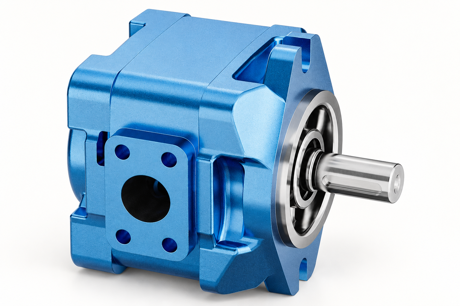
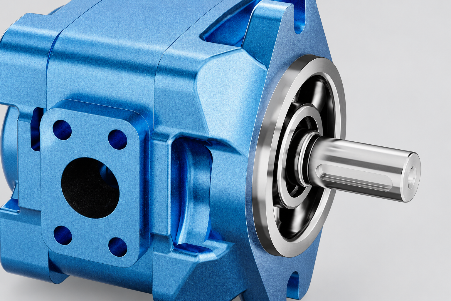
Prance's HG internal gear pump family is a relevant product reference for industrial pump-drive discussions. The illustrations show its catalogue housing and shaft. They do not establish its shaft-power curve, allowable speed range or a matching electric motor rating. Obtain the ordered pump performance data before selecting the prime mover.
Ask the supplier to state the assumptions behind the proposed motor size. A transparent selection should identify the controlling operating point, duty, starting condition and mechanical interface. A larger nominal size without this reasoning may increase cost while leaving the actual starting or cooling problem unresolved.
Verify the assembled power unit
During an approved commissioning test, record the pump's pressure, flow, speed and fluid temperature together with relevant drive measurements. Compare shaft demand calculations with the established efficiency assumptions. Monitor the motor through the intended cycle and check that unloading and protection operate as designed.
Electrical current alone is not a universal direct measure of pump shaft power. Supply voltage, power factor, motor efficiency and drive behaviour matter. Use suitable electrical measurement methods and the relevant motor data when comparing demand with a selection calculation.
Retain the operating-point table, final settings and test results. If demand is higher than expected, investigate pump losses, flow paths, pressure settings and mechanical alignment before increasing motor size. The final record should explain why the selected motor is suitable for the actual machine duty.
Frequently asked questions
Can I size the motor using pressure times flow alone?
That gives hydraulic output power. Motor sizing also needs pump losses, duty, acceleration, cooling and the drive arrangement. Use verified pump performance at the relevant operating points.
Should motor efficiency be included in the required shaft rating?
Keep shaft output and electrical input distinct. The pump's shaft demand determines mechanical output requirements. Motor efficiency helps estimate electrical demand and energy use, together with the complete drive data.
Is a fixed percentage of oversizing always appropriate?
No. A universal margin does not address every starting, thermal or control condition. Identify the controlling duty and use the motor manufacturer's selection process for that application.
Can a variable-speed drive run the pump at any speed?
No. Confirm pump speed limits, inlet requirements, motor cooling and drive capability across the proposed range. The full assembly must be suitable at both minimum and maximum operating conditions.
Why does an adequately rated motor trip during starting?
The actual acceleration torque, pressure loading, cold-fluid resistance or starting arrangement may differ from the running calculation. Review the torque-speed relationship and protection settings using qualified electrical and hydraulic personnel.
Related products and engineering guides
Internal Gear Pump HG for Plastic Injection Molding Machine, related hydraulic product range, Hydraulic Pump Power Calculation: kW, Horsepower, and Efficiency, Hydraulic Pump Torque Calculation: Formula, Units, and Motor Sizing, Multiple Hydraulic Pumps on One Drive: Torque and Power Checks. Provide the circuit, fluid, duty and exact ordered configuration when requesting component-specific data.
University lesson: mod-40 lec-42 AppendicesTutorial on Basic Calculation on HST System and Hydraulic Fluids
This NPTEL university lecture explains the component principles underlying this guide; the lecture is background education rather than a configuration-specific test procedure.

Technical references
- NPTEL: hydraulic power and efficiency
- US DOE: motor and drive system sizing
- NIOSH: hazardous-energy isolation
Sources support the stated principles and method scope. Illustrative inputs and another manufacturer’s documents do not establish Prance component ratings, warranties or brand affiliation.