شركة ونزهو برانس للمعدات الهيدروليكية المحدودة

تجاوز مضخة المعايرة بالضغط: لماذا يبدو الضغط الثابت طبيعيًا
Pressure-compensated pump overshoot happens when outlet demand falls faster than the pump can reduce displacement. Pressure briefly rises above the eventual controlled value, even though a slow gauge later looks normal. The useful diagnosis is a synchronized pressure and operating-event trace, followed by a review of pump control, relief behavior, and circuit volume. Turning down the compensator without identifying the event can hide the symptom while reducing useful machine performance.
This guide addresses repeated demand-change transients on variable-displacement pumps. It does not provide an adjustment sequence or a universal pressure allowance. The installed pump, control suffix, relief valve, and weakest connected component determine the permitted conditions. Stop operation when pressure exceeds a verified limit or when the machine shows leakage, unstable motion, or abnormal noise.
Separate three pressure values before changing anything
Identify the pressure immediately before the event, the highest credible transient pressure, and the pressure after the circuit settles. A compensator setting is associated with controlled operation; it is not a promise that every instantaneous pressure will remain at that value. Equally, a transient above the setting does not automatically prove the compensator is defective.
Record where each pressure is measured. A pump-outlet transducer and an actuator-port transducer may see different peaks because a valve, check valve, hose, or trapped volume separates them. If only the load port spikes while pump pressure remains controlled, the investigation must include load-induced compression and local valve events. Replacing the pump on that evidence alone is premature.
Use consistent units and references. Compare gauge pressure with gauge pressure, and distinguish the documented continuous, intermittent, and maximum permissible conditions. Do not convert an unspecified catalogue maximum into an acceptable repeated transient limit. Ask for the conditions attached to the rating, including duration and repetition where these are defined.
Why a pump keeps delivering after demand changes
Displacement control involves moving hydraulic and mechanical parts. Following a demand reduction, the control must sense the change and move the displacement mechanism. During this transition, delivered oil can exceed what the circuit accepts. Oil compressibility and the compliance of hoses and housings allow pressure to rise while flow and displacement rebalance.
ال Engineering Mechanics study listed below examines outlet-valve closure, pump speed, displacement, pressure overshoot, and control time. It supports treating these as dynamic variables rather than judging the pump solely by its final pressure. Its experimental arrangement is a research configuration, not an instruction to slam a valve shut on an operating machine.
For troubleshooting, identify the normal event that already produces the complaint: a directional valve returning to neutral, an actuator reaching a controlled stop, or a process demand being removed. Observe that event within the machine’s approved operating sequence. Deliberately creating a more severe closure is unnecessary and can damage connected components.
Build a trace that can capture the event
Choose a pressure transducer and recording chain with adequate range, overload capability, and dynamic response for the suspected transient. The sensor, adaptor, cable, signal conditioner, recorder, and software filtering all affect the result. A fast recorder cannot recover a peak removed by a heavily damped measurement connection.
Use the equipment manufacturer’s approved measurement points. Installation requires shutdown, isolation, stored-energy control, and confirmation that pressure has been relieved. Hydraulic accumulators and externally driven loads can retain or regenerate pressure after the power unit stops. Personnel should never loosen a fitting to determine whether pressure remains.
Capture the command or valve signal on the same time base as pressure when feasible. Motor speed and the operating load are useful additional channels. Keep the raw trace as well as a readable plot. State sampling settings and any filtering so a later reviewer can distinguish real ringing from data processing. A single unexplained maximum value is less useful than a repeatable waveform tied to a known event.
Use the waveform to narrow the investigation
The table is a qualitative diagnostic guide, not an acceptance standard. The cited transient and interaction research explains why control response and component combinations matter. The proposed checks below are engineering review steps that must remain inside the machine’s documented limits.
| نمط ملحوظ | Plausible direction for investigation | Check before deciding on a repair |
|---|---|---|
| Brief rise followed by a stable normal pressure | Demand falls before displacement reduces | Align the peak with valve command and compare approved operating speeds |
| Repeated pressure oscillations after closure | Pump control and another regulating element may interact | Identify every pressure controller and obtain their applicable response and setting instructions |
| Peak changes after a hose or manifold replacement | Circuit compliance, volume, or measurement location changed | Compare the old and new arrangement and inspect the actual sensor connection |
| Load-port peak without a matching pump-outlet peak | A local load or trapped-volume event | Review the intervening valves and actuator mechanics |
| Slow gauge normal while recorded trace rises sharply | Indicator response conceals the event | Confirm the recording chain and repeat under the same safe operating condition |
| Higher steady pressure as well as a transient peak | The problem extends beyond overshoot | Verify sensor calibration, control identification, and the approved setting procedure |
Review relief-valve interaction without removing protection
A compensator and a relief valve perform different jobs. One changes pump delivery; the other provides a pressure-dependent flow path. Their actions can overlap, depending on circuit design and operating conditions. The University of Saskatchewan research published by JFPS reports adverse interactions when pressure-limiting-device settings approach the pump compensator setting.
That finding does not establish one universal separation value. Obtain the pump and valve instructions for the actual circuit, including tolerances, flow-dependent characteristics, and response conditions. A nominal setting on a parts list does not describe the full relief behavior at transient flow. The supplier should review the combination when the machine repeatedly crosses between control modes.
Never block, isolate, or defeat the relief path to make the waveform look cleaner. If a protective device is suspected of contributing to instability, the next step is a controlled engineering review of its suitability and installation. Protection must remain effective throughout any authorized test. Record return pressure where it affects the installed valve’s operation, rather than assuming the tank reference is always zero.
Compare operating conditions one at a time
Start from the least demanding approved condition that reliably shows the event. Keep fluid temperature, load, speed, and command sequence consistent between captures. Where the machine permits a controlled change, vary one factor and explain why. Changing oil temperature, valve ramp, and speed together may improve the trace but will not identify the cause.
A peak that increases with speed suggests reviewing delivered flow and the time available for control response. A peak that changes primarily with the valve sequence points toward demand-transition timing. A temperature-dependent change warrants checking fluid condition and the control’s specified viscosity range. These are directions for investigation, not proofs of a single failed component.
Do not continue a speed sweep through an unstable or excessive-pressure region. Define stop conditions before testing. If the permitted envelope is unavailable, obtain it before reproducing the event. A lack of verified limits is a reason to narrow the test, not to infer a safe value from previous survival.
Connect the review to the correct pump configuration
Prance’s A10VO 31-series product page identifies a variable-displacement axial-piston pump for open-circuit applications. That provides a relevant product family for a displacement-control discussion. It does not establish the response time, pressure setting, overshoot limit, or control options of every supplied unit.
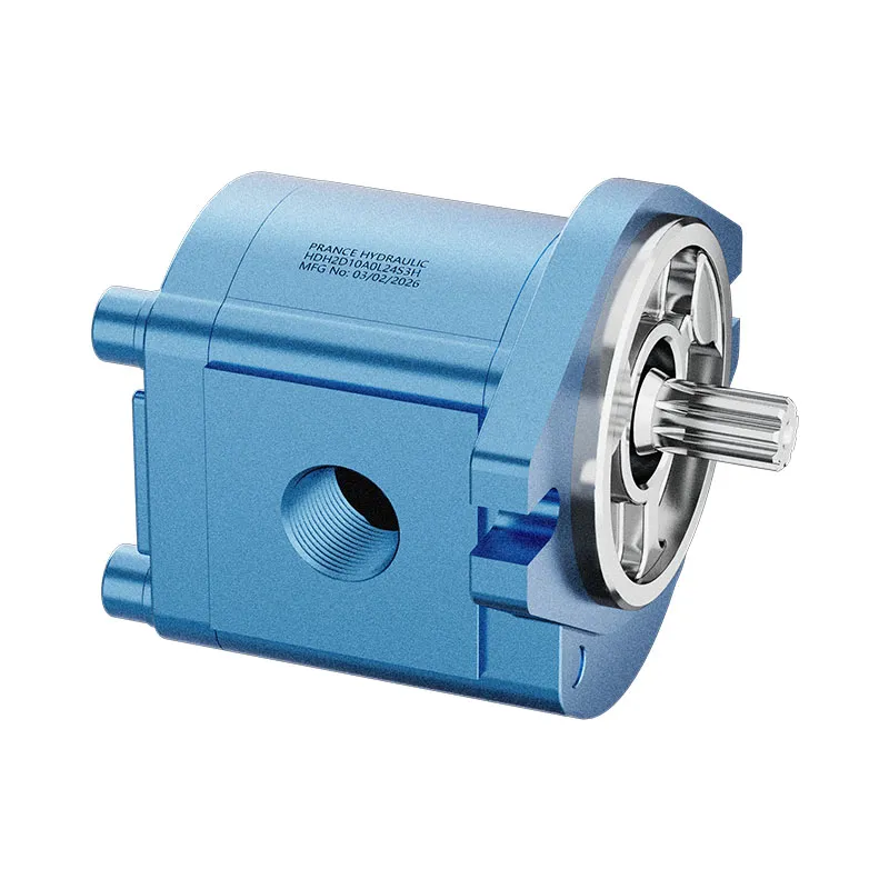
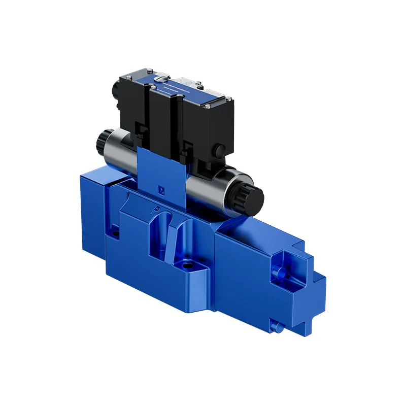
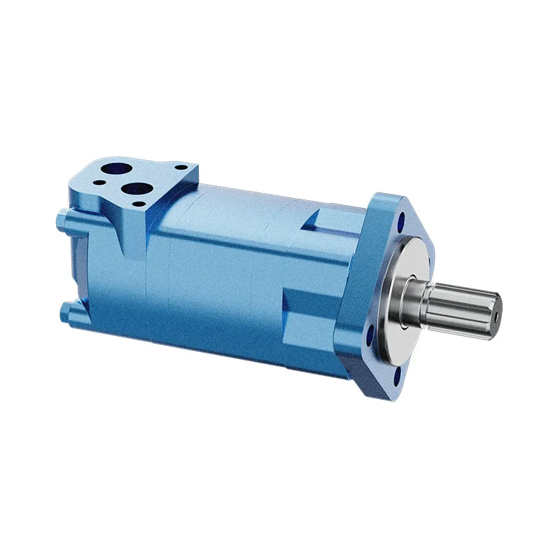
The original product photographs below show exterior views for identification. The exact supplied type and control arrangement must be confirmed from the complete order code and its documentation. Do not infer internal damping passages, spring settings, or interchangeable compensator assemblies from a photograph. Similar-looking pumps may require different control instructions.
There is also a limit to what a replacement quotation can solve. If the current unit meets its documented behavior but the circuit demands a faster transition, replacing it with an identical configuration may reproduce the same peak. Supply the waveform and circuit arrangement so the discussion addresses response compatibility as well as mounting and flow requirements.

Choose corrective action from the cause
When the measurement chain is responsible, correct the measurement and repeat the baseline before modifying hardware. When the normal valve command removes demand too abruptly, an approved control-sequence change may reduce the transient, but it must preserve stopping accuracy and machine safety. Longer transitions can affect cycle time and load control.
When evidence points to a control fault, use the manufacturer’s inspection and service procedure. Do not improvise orifice sizes, substitute springs, or adjust unidentified screws. Changes to pilot restrictions can affect stability and response elsewhere in the operating envelope, even if one captured peak improves.
When the circuit requires a different pressure-limiting arrangement or additional transient management, have the complete design reviewed. Accumulators introduce stored energy, precharge requirements, isolation needs, and their own failure modes. They are not a universal accessory to add after seeing a pressure peak. The engineering decision should include both the event being controlled and the consequences of the proposed change.

Verify the repair across the actual duty
Repeat the original measurement at the same point and settings. Compare peak pressure, settled pressure, event duration, and recovery behavior. A lower peak accompanied by prolonged oscillation or poor actuator stopping is not a satisfactory result. Check the other functions served by the power unit, including simultaneous operations where applicable.
Then verify approved cold and warmed operating conditions and relevant load cases. Document the conditions actually covered; do not label an entire machine validated after one unloaded cycle. Preserve the original trace and the final trace together with the change made. This allows maintenance personnel to recognize recurrence without guessing what was altered.
For a supplier review, provide the complete pump and control code, hydraulic diagram, relief identification, fluid and temperature, drive-speed range, affected operating sequence, transducer location, and synchronized trace. State whether the complaint began after maintenance or a circuit change. These details support a decision about control condition, component interaction, or application suitability instead of an unsupported pump replacement.
الأسئلة الشائعة
هل يمكن لقراءة مقياس الضغط الثابتة العادية أن تستبعد التجاوز؟
لا. يمكن لمؤشر بطيء أن يظهر الضغط المستقر مع فقدان قمة قصيرة. استخدم سلسلة تسجيل مناسبة وربط المسار بالحدث التشغيلي قبل اتخاذ قرار بوجود عابر أم لا.
Should I reduce the compensator setting immediately?
لا تتبع إلا إجراء ضبط محددًا ومعتمدًا بعد التحقق من متطلبات الدائرة. فقد يؤدي خفض الإعداد إلى تقليل ضغط التشغيل المفيد دون معالجة سبب الحالة العابرة أو التفاعل مع أنظمة التحكم الأخرى.
Does a larger relief valve always cure the peak?
No. Valve response, pressure-flow behavior, installation, return conditions, and interaction with the pump all matter. The complete protective arrangement needs review rather than selection by nominal flow capacity alone.
Can the product photograph identify the correct control adjustment?
No. Exterior similarity is insufficient. Confirm the complete supplied code and the matching control documentation before servicing or adjusting the pump.
What should be accepted after a repair?
Use documented component and machine limits across the approved duty conditions. Confirm a controlled transient, stable recovery, correct actuator behavior, and effective protection, with repeatable before-and-after evidence.
موارد المنتج والهندسة ذات الصلة
مضخة إزاحة متغيرة الأصلية A10VO سلسلة 31, نطاق منتجات المضخة الهيدروليكية, تعديل منظم ضغط مضخة هيدروليكية: الإجراءات والمخاطر, تعزيز ضغط مدخل المضخة: متى تحل مضخة التعزيز المشكلة بشكل أفضل من استخدام خط سحب أكبر؟. تأكيد رمز المنتج الكامل ومتطلبات التطبيق عند طلب مراجعة التكوين.
Technical references
- Dynamic properties of pressure compensated pump
- Pump and pressure limiting device interactions
- NIOSH control of hazardous energy
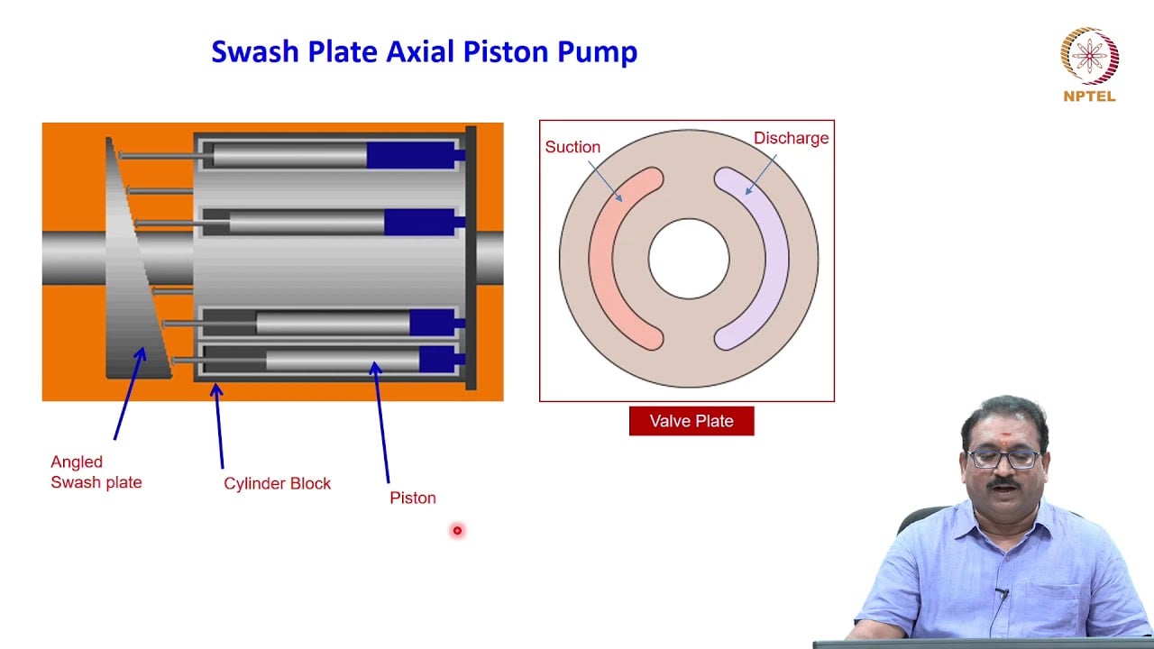
University lesson: hydraulic pumps
3.9 – Piston Pumps by NPTEL-NOC IITM provides background on pump operating principles. Axial-piston pump displacement mechanism provides background to destroking response; not model-specific transient data. It supplements the component fundamentals; it is not a test procedure for the complete circuit discussed above.