شركة ونزهو برانس للمعدات الهيدروليكية المحدودة


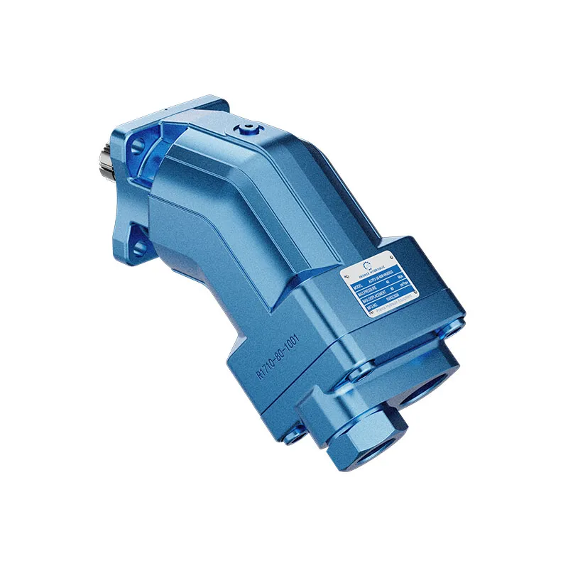
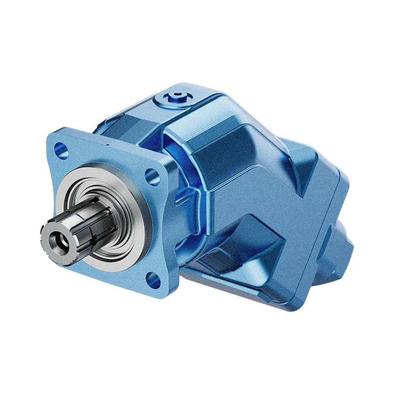
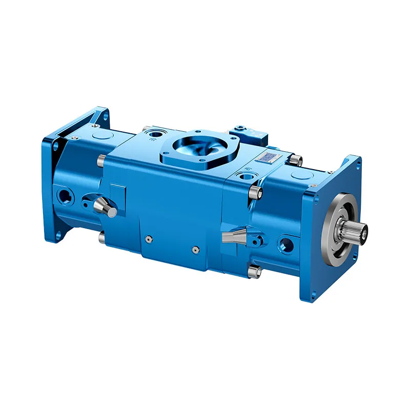
A17FO Series 10 Fixed Displacement Piston Pump
The A17FO Series 10 is a fixed displacement bent-axis piston pump offered for mobile drives. Its power take-off installation arrangement makes the drive interface, permitted rotation and available installation envelope central to a correct enquiry.
- Fixed displacement bent-axis design
- Mobile-drive application focus
- Power take-off installation described
- Sizes 23, 32, 45, 63, 80 and 107
PRANCE HYDRAULIC · PRODUCT SERIES
A17FO Series 10 Fixed Displacement Piston Pump
Axial piston; bent axis, fixed displacement · Confirm the selected mobile hydraulic circuit
The A17FO Series 10 is a fixed displacement bent-axis piston pump offered for mobile drives. Its power take-off installation arrangement makes the drive interface, permitted rotation and available installation envelope central to a correct enquiry.
Model
✓
Request a Quotationعرض البيانات الفنية وورقة البياناتA17FO Series 10Axial piston; bent axis, fixed displacement
Confirm the complete model and approved specification with Prance Hydraulic. Product-series references alone do not establish interchangeability.
Configuration review · Technical documentation · Product selection
تفاصيل المنتج
- Fixed displacement bent-axis design
- Mobile-drive application focus
- Power take-off installation described
- Sizes 23, 32, 45, 63, 80 and 107
CATEGORIES: مضخة إزاحة ثابتة, مضخة مكبسية
A17FO Series 10 Features & Application
Fixed displacement bent-axis design
For a fixed displacement, flow and speed remain linked by the selected displacement. Check the actual operating point and efficiency.
Mobile-drive application focus
Specify the full A17FO Series 10 order code, installation drawing and operating duty so the quotation can identify the proposed configuration.
Power take-off installation described
Compare the required flow at the actual drive speed and pressure. Check the selected variant rather than combining maxima from different rows.
Sizes 23, 32, 45, 63, 80 and 107
Include the series and all order-code suffixes in the enquiry. A common nominal size does not establish compatibility.
A17FO Series 10 Specifications
| Series / model | A17FO Series 10 |
|---|---|
| Product type | A17FO Series 10 Fixed Displacement Piston Pump |
| تصميم | Axial piston; bent axis, fixed displacement |
| Circuit / selection | Confirm the selected mobile hydraulic circuit |
| Listed nominal sizes | 23, 32, 45, 63, 80 and 107 |
| Listed geometric displacement | 22.9, 32, 45.6, 63, 80.4 and 106.7 cm³/rev |
A17FO Series 10 Selection & Configuration
The A17FO Series 10 is a fixed displacement bent-axis piston pump offered for mobile drives. Its power take-off installation arrangement makes the drive interface, permitted rotation and available installation envelope central to a correct enquiry.
Before ordering for a vehicle PTO, compare the spline, flange, engagement length and direction of rotation against the approved drawing. Required flow must be checked at the actual PTO speed, which can differ from the engine speed.

Your Application.
The Right Configuration.
Hydraulic pumps · Hydraulic motors · Hydraulic valves
Send the A17FO Series 10 nameplate, operating requirements and installation drawing for a configuration review before quoting.
- Model review — send the full model code or an existing nameplate photograph.
- Interface matching — confirm shaft, mounting flange, rotation and ports.
- Operating conditions — provide flow, pressure, speed, fluid and duty cycle.
- Documentation — request the relevant product data and drawings for your review.

A17FO Series 10 Buying Guide
Use this sequence to prepare the A17FO Series 10 configuration for review and quotation.
- Define required flow at the actual drive speed and continuous pressure.
- Identify peak pressure, duration and the work cycle.
- Confirm the selected displacement control and any auxiliary-drive requirement.
- Match rotation viewed from the shaft end, shaft, flange and ports.
- Review inlet conditions, drain routing and the installation envelope.
- Confirm fluid, viscosity, temperature, filtration and seals.
- Approve the complete model, control, drawing, quantity and delivery terms.
Selection, Documentation & Project Support

Selection Support
Learn more →Share your hydraulic circuit, operating point and installation requirements for a configuration discussion.
Flow · Pressure · Speed · Interfaces

Technical Resources
Learn more →Review product documentation, model codes and technical data before finalizing the specification.
Datasheets · Model codes · Drawings

Project Inquiries
Learn more →Send your required model, quantity, application and project requirements to discuss your inquiry.
Product inquiries · Configuration review
Configuration, Quantity & Delivery
Confirm the complete A17FO Series 10 code, approved drawing and operating limits. Availability, quantity, documentation and delivery date are confirmed in the quotation.
Discuss Your A17FO Series 10 Application
Send the full model code, operating duty, installation details and quantity.
Request a A17FO Series 10 QuotationA17FO Series 10 Questions Before Ordering
What type of product is the A17FO Series 10?
A17FO Series 10 Fixed Displacement Piston Pump. Design: Axial piston; bent axis, fixed displacement. Confirm the selected mobile hydraulic circuit. Confirm the complete order code for the offered version.
Can a similar pump replace the A17FO Series 10?
cURL Too many subrequests by single Worker invocation. To configure this limit, refer to https://developers.cloudflare.com/workers/wrangler/configuration/#limits.
cURL Too many subrequests by single Worker invocation. To configure this limit, refer to https://developers.cloudflare.com/workers/wrangler/configuration/#limits
Define required flow at the actual drive speed and continuous pressure. Identify peak pressure, duration and the work cycle. Attach the nameplate, complete order code, installation drawing and required quantity.
A17FO Series 10 Technical Data & Documents
View A17FO Series 10 catalog data and operating conditions
cURL Too many subrequests by single Worker invocation. To configure this limit, refer to https://developers.cloudflare.com/workers/wrangler/configuration/#limits.
البيانات الفنية
| حجم | غير مقبول | 23 | 32 | 45 | 63 | 80 | 107 | ||
| الإزاحة الهندسية لكل دورة | Vg | سم3 | 22.9 | 32 | 45.6 | 63 | 80.4 | 106.7 | |
| السرعة القصوى1) | nالاسمية2) | دورة في الدقيقة | 3050 | 2750 | 2650 | 2200 | 2150 | 2000 | |
| nالحد الأقصى3) | دورة في الدقيقة | 4300 | 3900 | 3800 | 3200 | 3100 | 2800 | ||
| صلابة الدوران | C | ك.ن.م/راديان | 2.56 | 3.12 | 4.18 | 6.25 | 8.73 | 11.2 | |
| عزم القصور الذاتي للمجموعة الدوارة | JTW | كجم متر2 | 0.0012 | 0.0012 | 0.003 | 0.0042 | 0.0072 | 0.0116 | |
| التسارع الزاوي الأقصى | α | راديان/ثانية2 | 6500 | 6500 | 14600 | 7500 | 6000 | 4500 | |
| حجم الحالة | V | l | 0.25 | 0.29 | 0.4 | 0.5 | 0.6 | 0.75 | |
| عزم الكتلة | TG | لا شيء جديد | 4.7 | 4.7 | 8.6 | 9.9 | 15.3 | 20 | |
| الكتلة (تقريبًا) | m | kg | 5.9 | 5.9 | 8.4 | 9.3 | 12.3 | 15.0 | |
تحديد خصائص التشغيل
ملاحظة
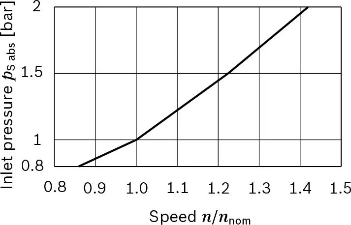
▶Theoretical values, without efficiency and tolerances;values rounded. ▶Operation above the maximum values or below the minimum values may result in a loss of function,a reduced service life or in the destruction of the axial piston unit. Other permissible limit values, such as speed variation, reduced angular acceleration as a function of the frequency and the permissible angular acceleration at start (lower than the maximum angular acceleration) can be found in data sheet 90261. 1) The values are applicable: – for the optimum viscosity range from νاختيار = 36 إلى 16 ملم2/s – for hydraulic fluids based on mineral oils. 2) The values apply at absolute pabs =1 بار عند منفذ الشفط S 3) الحد الأقصى للسرعة (حد السرعة) مع زيادة ضغط المدخل pabs عند منفذ الشفط S (انظر الرسم البياني).القوى المحورية المسموح بها لعمود القيادة
| حجم | غير مقبول | 23 | 32 | 45 | 63 | 80 | 107 | ||
| القوة المحورية القصوى، عند التوقف أو التشغيل بدون ضغط | 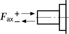 |
+Fax max | N | 0 | 0 | 0 | 0 | 0 | 0 |
| -Fax max | N | 24 | 33 | 43 | 53 | 60 | 71 | ||
ملاحظة
▶The values given are maximum values and do not apply to continuous operation. ▶The permissible axial force in direction -Fفأس is to be avoided as the lifetime of the bearing is reduced. ▶Radial forces are not permissible.Watch A17FO Series 10 Product Video
Related Selection Resources
Request a A17FO Series 10 Quotation
أخبرنا بالتكوين المطلوب، الكمية والتطبيق.
المنتجات ذات الصلة
Compare related hydraulic pumps and confirm the complete configuration for your application.

البيانات الفنية
| حجم | غير مقبول | 23 | 32 | 45 | 63 | 80 | 107 | ||
| الإزاحة الهندسية لكل دورة | Vg | سم3 | 22.9 | 32 | 45.6 | 63 | 80.4 | 106.7 | |
| السرعة القصوى1) | nالاسمية2) | دورة في الدقيقة | 3050 | 2750 | 2650 | 2200 | 2150 | 2000 | |
| nالحد الأقصى3) | دورة في الدقيقة | 4300 | 3900 | 3800 | 3200 | 3100 | 2800 | ||
| تدفق | عند nالاسمية | qv | ل/دقيقة | 70 | 88 | 121 | 139 | 173 | 213 |
| طاقة | عند nالاسمية و Δp= 350 بار | P | كيلوواط | 41 | 51 | 71 | 81 | 101 | 124 |
| عزم الدوران | عند Δp = 350 بار | T | لا شيء جديد | 127 | 178 | 254 | 351 | 448 | 594 |
| صلابة الدوران | C | ك.ن.م/راديان | 2.56 | 3.12 | 4.18 | 6.25 | 8.73 | 11.2 | |
| عزم القصور الذاتي للمجموعة الدوارة | JTW | كجم متر2 | 0.0012 | 0.0012 | 0.003 | 0.0042 | 0.0072 | 0.0116 | |
| التسارع الزاوي الأقصى | α | راديان/ثانية2 | 6500 | 6500 | 14600 | 7500 | 6000 | 4500 | |
| حجم الحالة | V | l | 0.25 | 0.29 | 0.4 | 0.5 | 0.6 | 0.75 | |
| عزم الكتلة | TG | لا شيء جديد | 4.7 | 4.7 | 8.6 | 9.9 | 15.3 | 20 | |
| الكتلة (تقريبًا) | m | kg | 5.9 | 5.9 | 8.4 | 9.3 | 12.3 | 15.0 | |
▼السرعة القصوى (السرعة المحدودة)
تحديد خصائص التشغيل
| تدفق | qv=(Vg×ن×ηv)/1000 | [ل/دقيقة] |
| عزم الدوران | T=(Vg×Δp)/(20×π×ηhm) | [نيوتن متر] |
| طاقة | P=(2π×T×ن)/60000=(qv×Δp)/(600×ηt) | [ك.و] |
مفتاح
Vg=الإزاحة لكل دورة [سم3]
Δp=الضغط التفريقي [بار]
n=السرعة [دورة/دقيقة]
ηv=الكفاءة الحجمية
ηhm=الكفاءة الهيدروليكية الميكانيكية
ηt=الكفاءة الكلية ( ηt=ηv × ηhm)
ملاحظة
▶القيم النظرية، بدون الكفاءة والتحملات؛ القيم مقربة.
▶العمل فوق القيم القصوى أو تحت القيم الدنيا قد يؤدي إلى فقدان الوظيفة، تقليل عمر الخدمة أو تدمير وحدة المكبس المحوري. يمكن العثور على قيم الحد المسموح بها الأخرى، مثل تغير السرعة، تقليل التسارع الزاوي كوظيفة للتردد والتسارع الزاوي المسموح عند البدء (أقل من التسارع الزاوي الأقصى) في ورقة البيانات 90261.
1) القيم تنطبق:
- لنطاق اللزوجة المثالي من νاختيار = 36 إلى 16 ملم2/s
- للسوائل الهيدروليكية المعتمدة على الزيوت المعدنية.
2) القيم تنطبق عند الضغط المطلق pabs =1 بار عند منفذ الشفط S
3) الحد الأقصى للسرعة (حد السرعة) مع زيادة ضغط المدخل pabs عند منفذ الشفط S (انظر الرسم البياني).
القوى المحورية المسموح بها لعمود القيادة
| حجم | غير مقبول | 23 | 32 | 45 | 63 | 80 | 107 | ||
| القوة المحورية القصوى، عند التوقف أو التشغيل بدون ضغط | |
+Fax max | N | 0 | 0 | 0 | 0 | 0 | 0 |
| -Fax max | N | 24 | 33 | 43 | 53 | 60 | 71 | ||
ملاحظة
▶القيم المعطاة هي قيم قصوى ولا تنطبق
على التشغيل المستمر.
▶القوة المحورية المسموح بها في الاتجاه -Fفأس يجب تجنبها حيث يتم تقليل عمر الحمل.
▶القوى الشعاعية غير مسموح بها.
