Wenzhou Prance Hydraulic Equipment Co., Ltd.


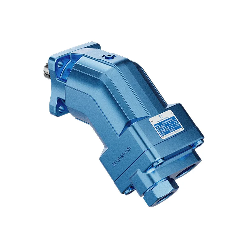
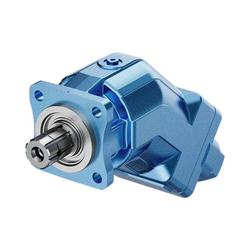
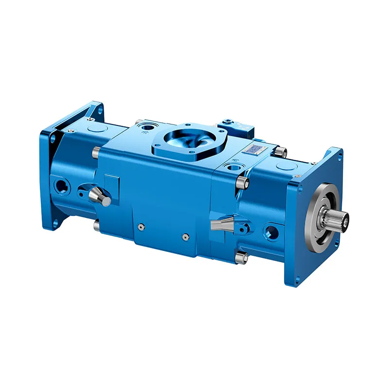
A17FO Series 10 Fixed Displacement Piston Pump
The A17FO Series 10 is a fixed displacement bent-axis piston pump offered for mobile drives. Its power take-off installation arrangement makes the drive interface, permitted rotation and available installation envelope central to a correct enquiry.
- Fixed displacement bent-axis design
- Mobile-drive application focus
- Power take-off installation described
- Sizes 23, 32, 45, 63, 80 and 107
PRANCE HYDRAULIC · PRODUCT SERIES
A17FO Series 10 Fixed Displacement Piston Pump
Axial piston; bent axis, fixed displacement · Confirm the selected mobile hydraulic circuit
The A17FO Series 10 is a fixed displacement bent-axis piston pump offered for mobile drives. Its power take-off installation arrangement makes the drive interface, permitted rotation and available installation envelope central to a correct enquiry.
Model
✓
Request a QuotationTechnische Daten & Datenblatt anzeigenA17FO Series 10Axial piston; bent axis, fixed displacement
Confirm the complete model and approved specification with Prance Hydraulic. Product-series references alone do not establish interchangeability.
Configuration review · Technical documentation · Product selection
Produktdetails
- Fixed displacement bent-axis design
- Mobile-drive application focus
- Power take-off installation described
- Sizes 23, 32, 45, 63, 80 and 107
CATEGORIES: Konstantpumpe, Kolbenpumpe
A17FO Series 10 Features & Application
Fixed displacement bent-axis design
For a fixed displacement, flow and speed remain linked by the selected displacement. Check the actual operating point and efficiency.
Mobile-drive application focus
Specify the full A17FO Series 10 order code, installation drawing and operating duty so the quotation can identify the proposed configuration.
Power take-off installation described
Compare the required flow at the actual drive speed and pressure. Check the selected variant rather than combining maxima from different rows.
Sizes 23, 32, 45, 63, 80 and 107
Include the series and all order-code suffixes in the enquiry. A common nominal size does not establish compatibility.
A17FO Series 10 Specifications
| Series / model | A17FO Series 10 |
|---|---|
| Product type | A17FO Series 10 Fixed Displacement Piston Pump |
| Design | Axial piston; bent axis, fixed displacement |
| Circuit / selection | Confirm the selected mobile hydraulic circuit |
| Listed nominal sizes | 23, 32, 45, 63, 80 and 107 |
| Listed geometric displacement | 22.9, 32, 45.6, 63, 80.4 and 106.7 cm³/rev |
A17FO Series 10 Selection & Configuration
The A17FO Series 10 is a fixed displacement bent-axis piston pump offered for mobile drives. Its power take-off installation arrangement makes the drive interface, permitted rotation and available installation envelope central to a correct enquiry.
Before ordering for a vehicle PTO, compare the spline, flange, engagement length and direction of rotation against the approved drawing. Required flow must be checked at the actual PTO speed, which can differ from the engine speed.

cURL Too many subrequests by single Worker invocation. To configure this limit, refer to https://developers.cloudflare.com/workers/wrangler/configuration/#limits.
cURL Too many subrequests by single Worker invocation. To configure this limit, refer to https://developers.cloudflare.com/workers/wrangler/configuration/#limits.
Hydraulic pumps · Hydraulic motors · Hydraulic valves
Send the A17FO Series 10 nameplate, operating requirements and installation drawing for a configuration review before quoting.
- Model review — send the full model code or an existing nameplate photograph.
- Interface matching — confirm shaft, mounting flange, rotation and ports.
- Operating conditions — provide flow, pressure, speed, fluid and duty cycle.
- Documentation — request the relevant product data and drawings for your review.

A17FO Series 10 Buying Guide
Use this sequence to prepare the A17FO Series 10 configuration for review and quotation.
- Define required flow at the actual drive speed and continuous pressure.
- Identify peak pressure, duration and the work cycle.
- Confirm the selected displacement control and any auxiliary-drive requirement.
- Match rotation viewed from the shaft end, shaft, flange and ports.
- Review inlet conditions, drain routing and the installation envelope.
- Confirm fluid, viscosity, temperature, filtration and seals.
- Approve the complete model, control, drawing, quantity and delivery terms.
Selection, Documentation & Project Support

Selection Support
Learn more →Share your hydraulic circuit, operating point and installation requirements for a configuration discussion.
Flow · Pressure · Speed · Interfaces

Technical Resources
Learn more →Review product documentation, model codes and technical data before finalizing the specification.
Datasheets · Model codes · Drawings

Project Inquiries
Learn more →Send your required model, quantity, application and project requirements to discuss your inquiry.
Product inquiries · Configuration review
Configuration, Quantity & Delivery
Confirm the complete A17FO Series 10 code, approved drawing and operating limits. Availability, quantity, documentation and delivery date are confirmed in the quotation.
Discuss Your A17FO Series 10 Application
Send the full model code, operating duty, installation details and quantity.
Request a A17FO Series 10 QuotationA17FO Series 10 Questions Before Ordering
What type of product is the A17FO Series 10?
A17FO Series 10 Fixed Displacement Piston Pump. Design: Axial piston; bent axis, fixed displacement. Confirm the selected mobile hydraulic circuit. Confirm the complete order code for the offered version.
Can a similar pump replace the A17FO Series 10?
cURL Too many subrequests by single Worker invocation. To configure this limit, refer to https://developers.cloudflare.com/workers/wrangler/configuration/#limits.
cURL Too many subrequests by single Worker invocation. To configure this limit, refer to https://developers.cloudflare.com/workers/wrangler/configuration/#limits
Define required flow at the actual drive speed and continuous pressure. Identify peak pressure, duration and the work cycle. Attach the nameplate, complete order code, installation drawing and required quantity.
A17FO Series 10 Technical Data & Documents
View A17FO Series 10 catalog data and operating conditions
cURL Too many subrequests by single Worker invocation. To configure this limit, refer to https://developers.cloudflare.com/workers/wrangler/configuration/#limits.
Technische Daten
| Größe | NG | 23 | 32 | 45 | 63 | 80 | 107 | ||
| Geometrisches Fördervolumen pro Umdrehung | Vg | cm3 | 22.9 | 32 | 45.6 | 63 | 80.4 | 106.7 | |
| Höchstgeschwindigkeit1) | nnom2) | U/min | 3050 | 2750 | 2650 | 2200 | 2150 | 2000 | |
| nMax3) | U/min | 4300 | 3900 | 3800 | 3200 | 3100 | 2800 | ||
| Verdrehsteifigkeit | C | kNm/rad | 2.56 | 3.12 | 4.18 | 6.25 | 8.73 | 11.2 | |
| Trägheitsmoment der Drehgruppe | JTW | kgm2 | 0.0012 | 0.0012 | 0.003 | 0.0042 | 0.0072 | 0.0116 | |
| Maximale Winkelbeschleunigung | α | rad/s2 | 6500 | 6500 | 14600 | 7500 | 6000 | 4500 | |
| Fallzahl | V | l | 0.25 | 0.29 | 0.4 | 0.5 | 0.6 | 0.75 | |
| Massenträgheitsmoment | TG | Machs gut | 4.7 | 4.7 | 8.6 | 9.9 | 15.3 | 20 | |
| Masse (ca.) | m | kg | 5.9 | 5.9 | 8.4 | 9.3 | 12.3 | 15.0 | |
Bestimmung der Betriebskennlinien
Notiz
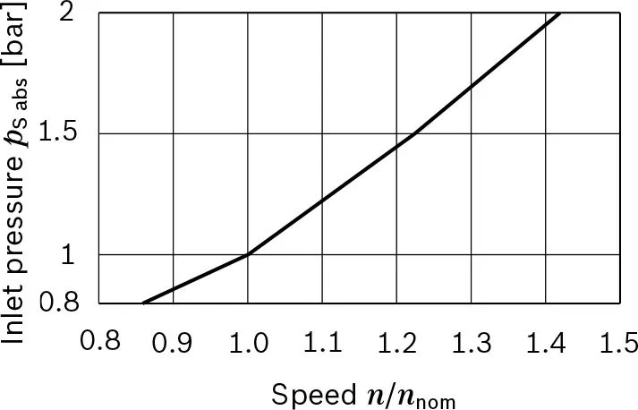
▶Theoretical values, without efficiency and tolerances;values rounded. ▶Operation above the maximum values or below the minimum values may result in a loss of function,a reduced service life or in the destruction of the axial piston unit. Other permissible limit values, such as speed variation, reduced angular acceleration as a function of the frequency and the permissible angular acceleration at start (lower than the maximum angular acceleration) can be found in data sheet 90261. 1) The values are applicable: – for the optimum viscosity range from νentscheiden = 36 bis 16 mm2/s – for hydraulic fluids based on mineral oils. 2) The values apply at absolute pABS = 1 bar am Sauganschluss S 3) Höchstgeschwindigkeit (Geschwindigkeitsbegrenzung) bei erhöhtem Eingangsdruck pABS am Saugstutzen S (siehe Diagramm).Zulässige Axialkräfte der Antriebswelle
| Größe | NG | 23 | 32 | 45 | 63 | 80 | 107 | ||
| Maximale Axialkraft, im Stillstand oder drucklosen Betrieb | 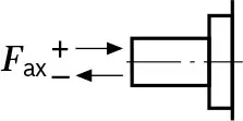 |
+FAch, Max | N | 0 | 0 | 0 | 0 | 0 | 0 |
| -FAch, Max | N | 24 | 33 | 43 | 53 | 60 | 71 | ||
Notiz
▶The values given are maximum values and do not apply to continuous operation. ▶The permissible axial force in direction -FAxt is to be avoided as the lifetime of the bearing is reduced. ▶Radial forces are not permissible.Watch A17FO Series 10 Product Video
Related Selection Resources
Request a A17FO Series 10 Quotation
Tell us your required configuration, quantity and application.
Ähnliche Produkte
Compare related hydraulic pumps and confirm the complete configuration for your application.

Technische Daten
| Größe | NG | 23 | 32 | 45 | 63 | 80 | 107 | ||
| Geometrisches Fördervolumen pro Umdrehung | Vg | cm3 | 22.9 | 32 | 45.6 | 63 | 80.4 | 106.7 | |
| Höchstgeschwindigkeit1) | nnom2) | U/min | 3050 | 2750 | 2650 | 2200 | 2150 | 2000 | |
| nMax3) | U/min | 4300 | 3900 | 3800 | 3200 | 3100 | 2800 | ||
| Fluss | bei nnom | qv | l/min | 70 | 88 | 121 | 139 | 173 | 213 |
| Macht | bei nnom und Δp = 350 bar | P | kW | 41 | 51 | 71 | 81 | 101 | 124 |
| Drehmoment | bei Δp = 350 bar | T | Machs gut | 127 | 178 | 254 | 351 | 448 | 594 |
| Verdrehsteifigkeit | C | kNm/rad | 2.56 | 3.12 | 4.18 | 6.25 | 8.73 | 11.2 | |
| Trägheitsmoment der Drehgruppe | JTW | kgm2 | 0.0012 | 0.0012 | 0.003 | 0.0042 | 0.0072 | 0.0116 | |
| Maximale Winkelbeschleunigung | α | rad/s2 | 6500 | 6500 | 14600 | 7500 | 6000 | 4500 | |
| Fallzahl | V | l | 0.25 | 0.29 | 0.4 | 0.5 | 0.6 | 0.75 | |
| Massenträgheitsmoment | TG | Machs gut | 4.7 | 4.7 | 8.6 | 9.9 | 15.3 | 20 | |
| Masse (ca.) | m | kg | 5.9 | 5.9 | 8.4 | 9.3 | 12.3 | 15.0 | |
▼Höchstgeschwindigkeit (Geschwindigkeitsbegrenzung)
Bestimmung der Betriebskennlinien
| Fluss | qv=(Vg×n×ηv)/1000 | [l/min] |
| Drehmoment | T=(Vg×Δp)/(20×π×ηhm) | [Nm] |
| Macht | P=(2π×T×n)/60000=(qv×Δp)/(600×ηt) | [kW] |
Schlüssel
Vg= Verdrängung pro Umdrehung [cm3]
Δp = Differenzdruck [bar]
n = Drehzahl [U/min]
ηvVolumetrischer Wirkungsgrad
ηhmHydraulisch-mechanischer Wirkungsgrad
ηt= Gesamtwirkungsgrad ( ηt=ηv × ηhm)
Notiz
▶ Theoretische Werte, ohne Wirkungsgrad und Toleranzen; Werte gerundet.
Der Betrieb oberhalb der Maximalwerte oder unterhalb der Minimalwerte kann zu Funktionsverlust, einer verkürzten Lebensdauer oder zur Zerstörung der Axialkolbeneinheit führen. Weitere zulässige Grenzwerte wie Drehzahländerung, frequenzabhängige reduzierte Winkelbeschleunigung und zulässige Winkelbeschleunigung beim Start (kleiner als die maximale Winkelbeschleunigung) sind dem Datenblatt 90261 zu entnehmen.
Die Werte gelten:
- für den optimalen Viskositätsbereich von νentscheiden = 36 bis 16 mm2/s
- für Hydraulikflüssigkeiten auf Mineralölbasis.
2) Die Werte gelten bei absolutem pABS = 1 bar am Sauganschluss S
3) Höchstgeschwindigkeit (Geschwindigkeitsbegrenzung) bei erhöhtem Eingangsdruck pABS am Saugstutzen S (siehe Diagramm).
Zulässige Axialkräfte der Antriebswelle
| Größe | NG | 23 | 32 | 45 | 63 | 80 | 107 | ||
| Maximale Axialkraft, im Stillstand oder drucklosen Betrieb | |
+FAch, Max | N | 0 | 0 | 0 | 0 | 0 | 0 |
| -FAch, Max | N | 24 | 33 | 43 | 53 | 60 | 71 | ||
Notiz
Die angegebenen Werte sind Höchstwerte und gelten nicht
in den Dauerbetrieb.
▶Die zulässige Axialkraft in Richtung -FAxt ist zu vermeiden, da sich dadurch die Lebensdauer des Lagers verkürzt.
▶Radiale Kräfte sind nicht zulässig.
