Wenzhou Prance Hydraulic Equipment Co., Ltd

Hydraulic Flow Regulator Valve: Hold Speed Steady Under Changing Load
A hydraulic flow regulator valve meters oil so actuator speed stays closer to the intended setting when load or supply pressure changes. In technical usage it usually means a pressure-compensated flow control—an orifice plus a compensator—rather than a bare needle throttle. The sections below separate that job from priority and divider branches, place meter-in / meter-out / bleed-off in context, flag heat on continuous duty, and list the circuit facts worth gathering before a valve conversation.
What a hydraulic flow regulator valve is
Flow regulation is how designers control actuator speed by regulating flow rate. A hydraulic flow regulator valve is the flow-control device that does that job when a buyer asks for steadier speed under changing load.
In plain language, it helps set how fast a cylinder or motor moves, and often tries to keep that speed steadier when the load shifts. A distributor who receives a request for a “flow regulator” should confirm speed control is the intended job before comparing packages.
Technical catalogues often reserve “flow regulator” for a pressure-compensated arrangement: a metering orifice that senses pressure drop, plus a compensating piston that adjusts as inlet or outlet pressure varies. That framing is the primary entity of this article.
Needle throttle vs pressure-compensated flow regulator
A needle valve is a non-compensated variable orifice. Flow through that orifice depends on orifice size, pressure difference across the orifice, and oil temperature or viscosity.
An OEM that sees speed drift when load weight changes is often looking at that three-variable behavior. A simple throttle can be enough when load and supply stay steady; it is a weaker choice when those pressures move and constant speed still matters.
A pressure compensated flow control holds essentially constant volume flow by keeping the pressure drop across the metering orifice with a compensator. The compensator spool or piston adjusts so the set flow stays closer to target when inlet or load pressure shifts.
Market packages sometimes add a reverse-flow check so metering works in one direction while reverse free flow is available through the check. That packaging detail does not turn a needle into a compensator; it only describes how reverse oil is handled.
| Device | Core behavior | Plain-language picture | First buyer question |
|---|---|---|---|
| Needle valve / non-compensated orifice | Flow changes with orifice size, ΔP, and viscosity | A simple throttle whose speed can drift when load or oil temperature changes | Is load and supply steady enough for a non-compensated throttle? |
| Pressure-compensated flow regulator | Compensator holds ΔP across the metering orifice | It adjusts itself so set flow stays closer to target when pressures shift | Do we need steadier speed under varying load or supply? |
| Priority valve / 3-way flow regulator | Supplies set primary flow, then bypasses excess | Feeds a critical function first, then sends leftover oil elsewhere | Is the job protecting a primary branch before secondary flow? |
| Flow divider | Splits one inlet into two outlets (equal or ratio) | Shares one supply between two branches | Is the job splitting flow rather than holding one branch set speed? |
Priority regulators and flow dividers: related, not identical
A priority valve / 3-way flow regulator supplies set flow to a primary circuit and bypasses excess to a secondary path. It behaves as pressure-compensated flow control for the primary branch, then routes surplus elsewhere.
A buyer who asks for “priority flow” is describing a branching problem, not a single-branch restrictive regulator on one work line. Collapsing those labels into one SKU request hides whether primary protection or simple metering is the real need.
A flow divider splits one input into two outputs at equal or ratio shares. It cannot alone guarantee precise actuator synchronization. Equal-ratio splitting and primary-first priority are different branching tools; neither replaces a two-way restrictive regulator on a single actuator line.
When the enquiry mentions a priority flow divider, record whether the buyer means primary-first bypass or equal-ratio split before comparing hardware. That short clarification keeps related devices from being treated as interchangeable.
Meter-in, meter-out, and bleed-off placement
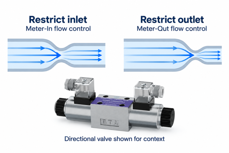
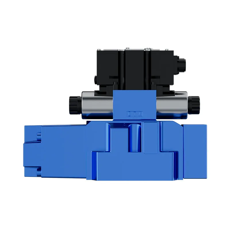
Meter-in / meter-out / bleed-off describe where flow is restricted relative to the actuator. Placement changes how speed is controlled and how much energy is dissipated as heat.
Meter-in restricts oil entering the actuator. Meter-out restricts oil leaving it. Bleed-off diverts excess toward tank or another path so only part of the pump flow reaches the work.
Confirm the architecture against the circuit plan rather than treating location as a universal rule. The same regulator style can behave differently when it sits before a cylinder, after a motor, or on a bleed path that runs continuously.
Placement also interacts with heat. A partially open valve with a large pressure drop converts that drop into fluid temperature rise whether the oil is metering into work or dumping toward tank.
What flow regulation is not
Flow regulation meters volume for actuator speed. It is not system overpressure protection, circuit diversion, or directional start/stop/direction control.
A relief valve limits pressure; a flow regulator does not replace that pressure-protection job. Buyers who hope a flow valve will “keep pressure” while cutting flow are mixing two function families. For pressure-setting procedure, use the Hydraulic Relief Valve Setting Guide.
Path switching and selector diversion belong to diverter-style conversations, not this speed-control taxonomy. Directional start, stop, and direction of flow belong to directional spool routes such as the directional valve 4WE discussed later.
A generic control-valve family overview can list flow as one of three function families. This article stays on the flow-regulator framing rather than rewriting that overview.
Heat and continuous-duty objections buyers actually raise
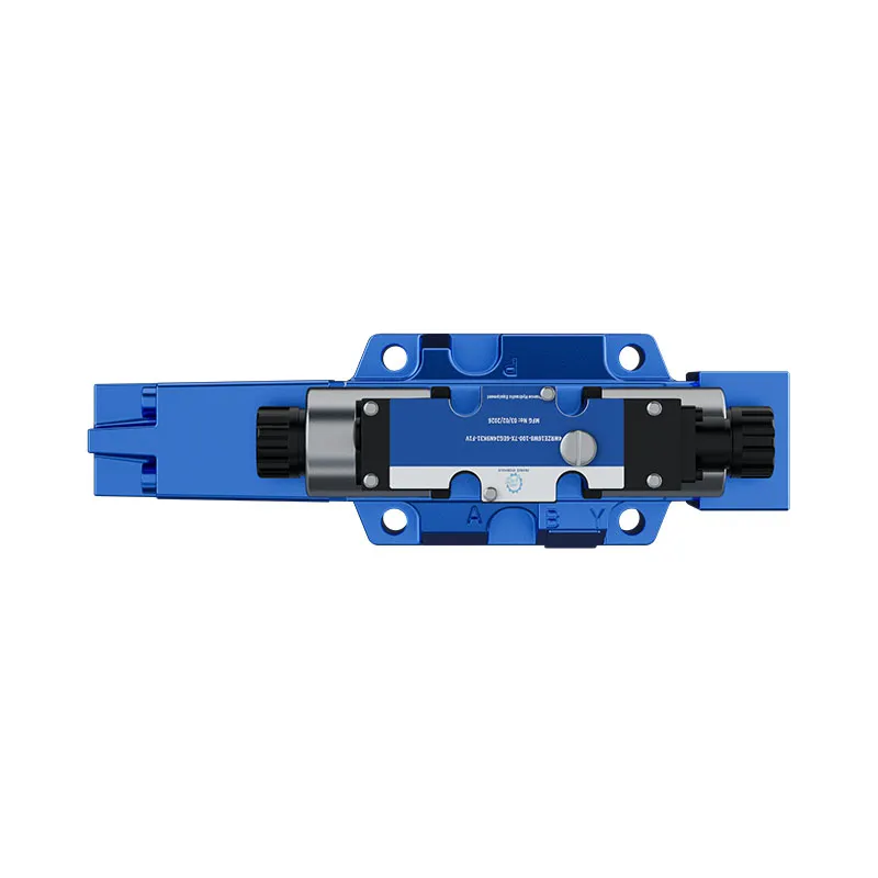
Throttling requires pressure drop, and that drop converts excess energy into heat—especially on continuous motor duty. A flow valve is not a free way to cut flow while “keeping pressure.”
From the field: In a TractorByNet discussion of flow control valves, a buyer asked whether adding a flow control to reduce flow while maintaining pressure was a simple fix. Replies noted that flow controls need some pressure drop to operate, that excess oil returned to tank is energy loss or heat, and that continuous motor duty makes that heat a real concern.
Operators who later see rising oil temperature around a partially open flow valve are often seeing that same pressure-drop-to-heat conversion. That complaint belongs beside speed-control selection; it is not a cooler-sizing procedure and it is not a relief-valve diagnosis guide.
Record duty context early. Intermittent cylinder moves and continuous motor loads do not stress a throttling path the same way, even when the set flow number looks similar on paper.
Build the selection picture before a valve conversation
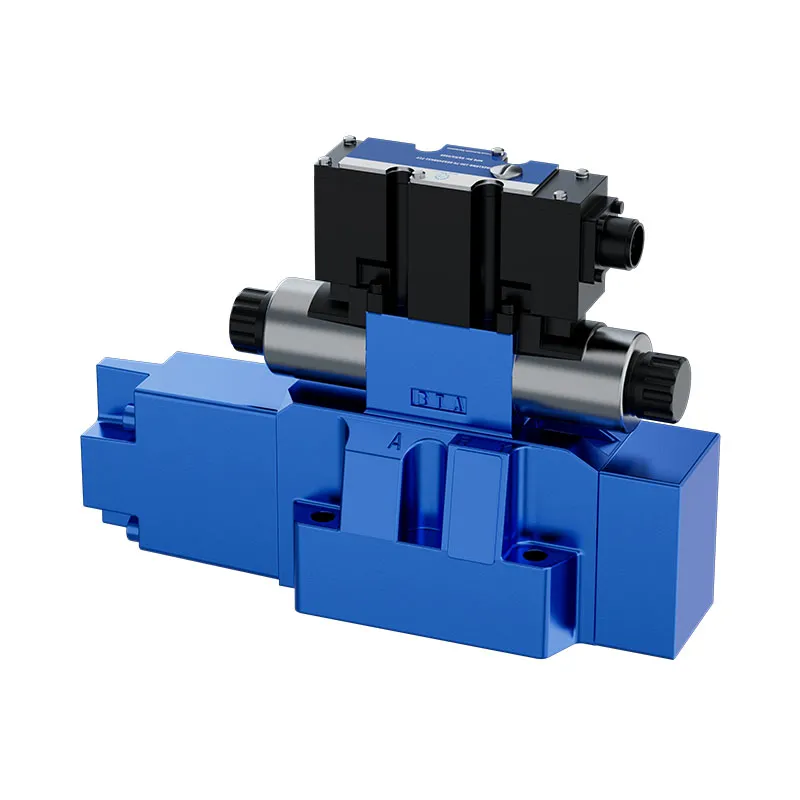
Gather circuit function, flow, pressure, control signal, mounting, ports, fluid, and filtration or cleanliness before treating a flow-regulator style solution as the next step. Those facts turn taxonomy into a conversation a supplier can continue.
Prance publishes a hydraulic valves hub covering directional and proportional options. Buyers are asked to start with circuit function, flow, pressure, control signal, mounting, and fluid-cleanliness requirements.
| Information to gather | Why it belongs in the conversation | Example clarification |
|---|---|---|
| Circuit function | Separates speed metering from path, priority, divider, or pressure jobs | Is the need single-branch speed control, primary-first priority, flow split, or something else? |
| Required flow and working pressure | Ties the valve discussion to circuit demand | What flow and working pressure does the machine use in normal operation? |
| Control signal / electrical interface | Defines how any powered valve will be driven | Manual adjustment, solenoid, or continuous command—and which electrical interface applies? |
| Compensator body mount and work-line porting | Confirms how the flow-regulator package will sit and connect on the metered branch | Subplate, inline body, or manifold face—and which work-line ports feed the orifice/compensator path? |
| Oil grade plus filtration for continuous throttling | Captures fluid condition where orifice ΔP and compensator response must stay stable | Which hydraulic oil grade is in use, and what filtration rating supports steady set-flow under load? |
| Duty context | Flags continuous throttling heat risk | Is the load intermittent cylinder motion or continuous motor duty? |
A procurement reader who collects those inputs before contacting a supplier avoids asking a model code to invent the missing circuit story.
Industrial compensated flow-control valves also have standardized mounting-surface practice under ISO 6263 for interchangeability of mounting surfaces. That note helps when a drawing calls out compensated flow-control mounting; it does not invent a Prance flow-regulator SKU or rating.
Product context: hydraulic valves hub and adjacent 4WE / 4WRAE routes
After the checklist above is filled in as far as the machine data allows, open the Hydraulic Valves family route. Prance publishes a hydraulic-valve product-family route covering directional and proportional options and asks for those same circuit-function, flow, pressure, control-signal, mounting, and fluid-cleanliness inputs.
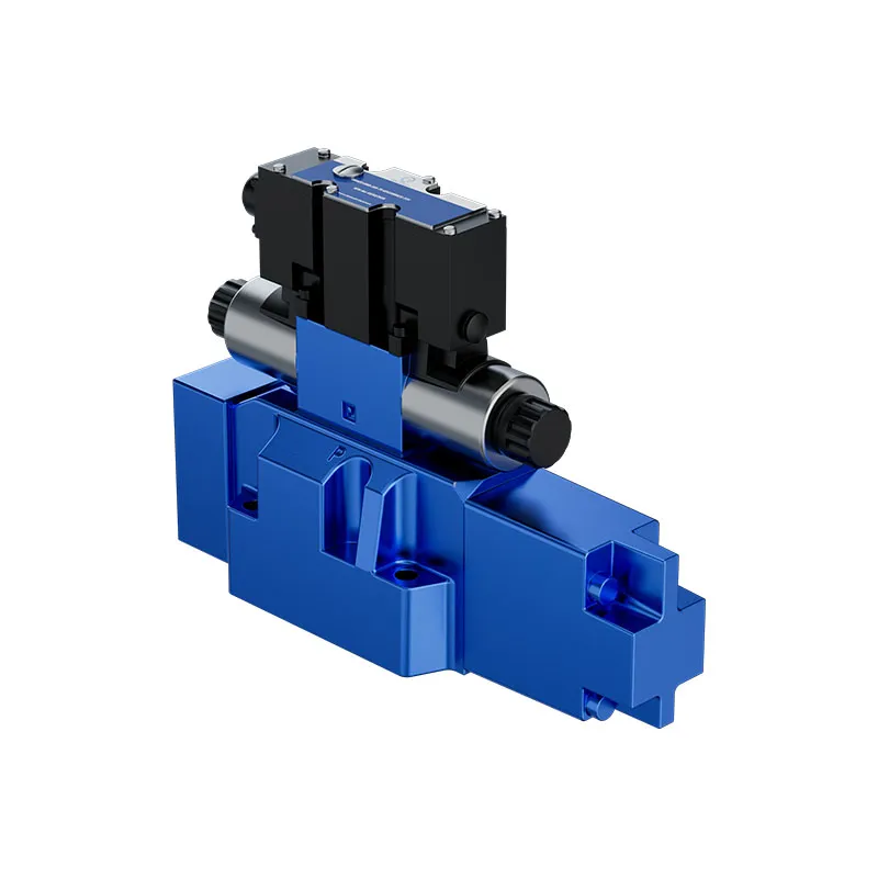
When the job is start, stop, and direction of flow rather than discrete flow regulation, review the Directional Valve 4WE route. 4WE6 / 4WE10 solenoid-operated directional spool valves control start, stop, and direction of flow. RFQ inputs there include flow, pressure, circuit/spool function, electrical interface, mounting, ports, fluid, and filtration class.
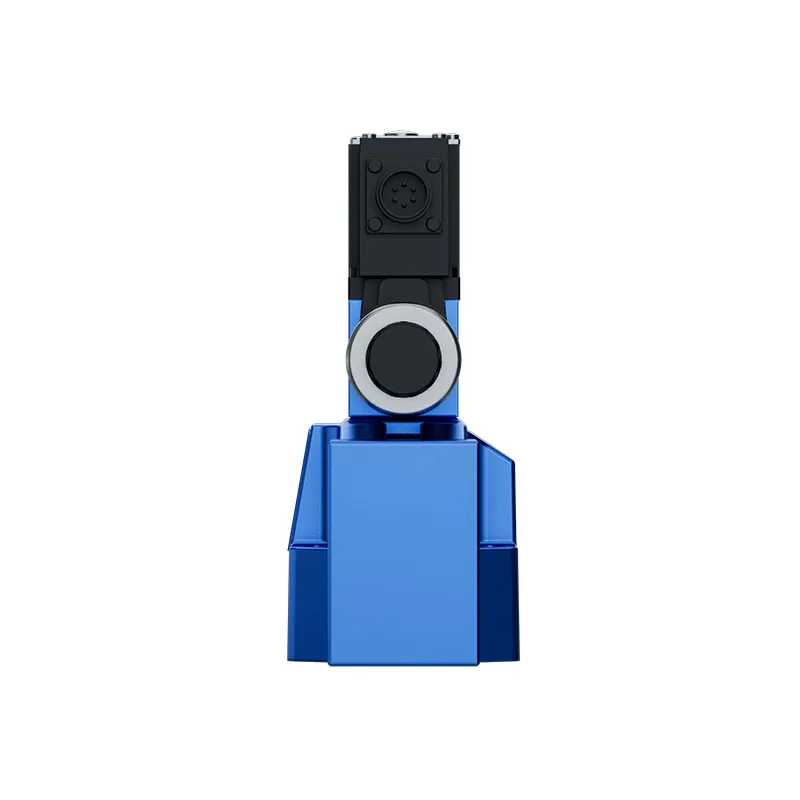
When continuous open-loop command of direction and volume flow is required, review the Proportional Valve 4WRAE route. 4WRAE is a direct-actuated proportional valve for controlling direction and volume flow in open-loop control with a spring-centred control spool. Selection still requires circuit function, flow, pressure, electrical/command interface, mounting, and fluid cleanliness confirmation.
Neither named route is a dedicated flow-regulator model. Use them when the documented job matches—path control for 4WE, continuous direction-and-volume command for the proportional valve 4WRAE—after the speed-control taxonomy and circuit facts are clear.
FAQs
What is a hydraulic flow regulator valve?
It is a flow-control device used to regulate actuator speed by metering flow. In technical usage, “flow regulator” usually points to a pressure-compensated arrangement rather than a bare needle throttle.
How does a pressure-compensated flow regulator work?
A metering orifice sets the target flow while a compensator holds the pressure drop across that orifice nearly constant. As inlet or load pressure changes, the compensator adjusts so volume flow stays closer to the set value.
How is a needle valve different from a flow regulator?
A needle valve is a non-compensated variable orifice whose flow changes with orifice size, pressure difference, and oil viscosity or temperature. A pressure-compensated flow regulator adds a compensator so set flow holds steadier under changing pressure. Some one-way packages also include a reverse-flow check for free reverse flow.
How does a flow regulator differ from a priority valve or flow divider?
A restrictive flow regulator typically meters one branch. A priority valve / 3-way flow regulator protects set primary flow and bypasses excess. A flow divider splits one inlet into two outlets and is not by itself a precise synchronization tool.
Does using a flow control valve create heat?
Yes. Throttling needs pressure drop, and that energy often becomes heat—especially when excess oil returns to tank on continuous duty. That observation is a selection warning, not a cooler-sizing procedure.
Can a flow regulator replace a relief valve?
No—a flow regulator meters flow for speed control, while a relief valve provides overpressure protection. Mixing those jobs leaves the circuit without a clear pressure-limit device.
What should I prepare before an RFQ about valves for speed control?
Prepare circuit function, required flow, working pressure, control signal or electrical interface, mounting, ports, fluid, and filtration or fluid-cleanliness class. Add duty context when continuous motor loads are in play.
Does Prance list a dedicated flow-regulator model on the valve hub?
The live hydraulic valves hub emphasizes directional and proportional options and asks for circuit-function RFQ inputs. Bring those circuit facts to the hub; do not invent a dedicated flow-regulator SKU. Use directional valve 4WE for start/stop/direction and proportional valve 4WRAE when continuous open-loop direction and volume flow is required.