Wenzhou Prance Hydraulic Equipment Co., Ltd

Hydraulic Valve Cavitation Noise: Pressure Drop at the Metering Edge
Hydraulic valve cavitation noise can arise when oil accelerates through a metering restriction, its local absolute pressure falls sufficiently, and vapor cavities subsequently collapse as pressure recovers. A positive pressure reading at the valve outlet does not prove that pressure remained adequate inside the restriction. However, noise alone cannot confirm cavitation: turbulent flow, entrained air, relief instability, and mechanical vibration can sound similar. Diagnose the pressure and operating conditions around the valve before changing a spool or adding back pressure. This guide concerns the metering edge, rather than pump-inlet starvation or a general pressure-drop calculation.
Follow the pressure through the restriction
Pressure is not uniform through a partly open valve. The fluid accelerates toward the smallest effective flow area and then enters a larger downstream passage. Static pressure can reach a local minimum before recovering to the pressure measured at a downstream test point. The difference between that local minimum and the outlet reading explains why two ordinary gauges cannot directly reveal every condition inside the valve.
NPTEL’s fluid-mechanics lesson describes cavitation as vapor formation in a local low-pressure region followed by collapse in a higher-pressure region. Near a solid surface, collapse can damage material. Apply that physical explanation to the valve’s actual flow path; do not interpret a generic diagram as proof of the location or severity of damage in an installed valve.
The ISA explanation of choked control-valve flow distinguishes cavitation from flashing. In cavitation, pressure recovery permits vapor collapse. If downstream conditions keep vapor present, the behavior is different. Neither condition should be assigned solely from an audible recording. Fluid properties, temperature, local geometry, and pressure conditions all affect the interpretation.
Separate vapor cavitation from air-related noise
Hydraulic oil can contain dissolved gas and entrained air. Air introduced elsewhere may pass through a valve, while low local pressure can also release gas from solution. Vapor formation and gas release are related to low pressure but are not identical mechanisms. A foaming reservoir points to an air-management investigation as well as any valve review.
Inspect the system history before blaming a metering edge. Recent hose work, low reservoir level, a disturbed suction connection, or changed return arrangements can introduce another explanation. If several valves become noisy together after the same maintenance event, investigate their shared supply and fluid condition. A single noisy operating position suggests a more localized comparison, but still does not prove cavitation.
Do not attempt to identify the mechanism by loosening fittings or opening a pressurized line. Use approved instruments and safe sampling procedures. Where visual inspection of the oil is relevant, collect a sample under the established procedure and record the time and conditions. Bubbles disappearing in a sample jar do not establish the pressure history inside the valve.
Record the operating point, not just the sound
Record upstream pressure, downstream pressure, flow, oil temperature, valve command, and actuator direction together. Include load state. A valve that is quiet while moving an unloaded cylinder may behave differently while controlling a descending load. Comparison requires the same relevant operating conditions, not just the same machine and nominal pump setting.
Measure at approved points close enough to represent the valve connections, and account for the intervening passages. A return-line gauge near the reservoir may miss a restriction between that point and the valve. Similarly, pump pressure is not automatically the inlet pressure at a remote valve bank. Label every measurement location on the schematic.
Record when noise begins and ends during a command sweep permitted by the machine procedure. A narrow noisy range can help an engineer relate the symptom to metering behavior. Do not dwell in an unstable or damaging condition simply to obtain a smoother recording. Stop if vibration, temperature, leakage, or machine response becomes unacceptable.
Use a diagnostic comparison table
This table is an author-proposed troubleshooting aid. It contains no universal cavitation threshold or allowable sound level. Use it to select the next investigation, then compare findings with the specific component and machine documentation.
| Observation | What it may suggest | What to verify next |
|---|---|---|
| Noise appears across one metering range | Local flow condition or control instability | Command, flow, pressure pair, and load at onset |
| Several valves become noisy together | Shared supply or fluid-condition change | Aeration, temperature, inlet condition, and recent maintenance |
| Noise changes when downstream conditions change | Sensitivity to pressure recovery or circuit interaction | Actual valve-outlet pressure and approved return limits |
| Noise follows a lowering or overrunning movement | Load control or insufficient makeup supply | Circuit function, actuator behavior, and protective valves |
| A high-pitched electrical hum occurs without flow | Electrical or mechanical source remains possible | Coil supply and mounting condition under safe inspection |
| Surface damage is found after removal | Cavitation erosion is one possible cause | Damage location, contamination evidence, and pressure history |
Keep observations separate from conclusions in the service record. “Noise at 35 percent command during lowering” is useful evidence. “Cavitation because the valve is loud” closes the investigation before the mechanism has been demonstrated.
Why adding back pressure requires a circuit review
Changing downstream pressure can change the local conditions at a restriction, but that does not make a return restriction a universal remedy. The new pressure affects other components connected to the same path. Pilot drains, seals, valve returns, and actuator loads may have different permissible conditions from the main pressure line.
Ask which passage would see the added pressure and which functions operate simultaneously. A change that reduces noise at one valve may increase heating, alter actuator force, or disturb another control. Review the complete circuit and component limits before selecting any hardware or setting. Never partially close an isolation valve as an improvised long-term solution.
A useful engineering comparison considers several options: reduce the pressure difference that must be dissipated, change the operating sequence, select an appropriate metering configuration, or use a specifically designed pressure-management arrangement. The choice depends on the load and control requirement. A quieter result must still meet speed, stability, temperature, and safety requirements.
Distinguish cavitation from ordinary throttling loss
Pressure drop and cavitation are different questions. Pressure drop tells you about the difference between two measured points; cavitation concerns whether local pressure and subsequent recovery create cavities and collapse. The same overall pressure drop can produce different internal conditions in different valve geometries. A catalog flow curve alone is not a complete cavitation assessment.
For an illustrative energy check, 20 L/min through a 50 bar pressure drop corresponds to approximately 1.67 kW of hydraulic power dissipated across that path, using flow multiplied by pressure difference and divided by 600. This is an example, not a Prance valve rating. It quantifies a thermal burden but does not calculate the internal minimum pressure or predict erosion.
If sustained throttling is unnecessary, the design review should ask why that pressure difference exists. If it is required for load control, removing it indiscriminately can create another problem. Preserve the intended motion-control function while evaluating a suitable pressure distribution and valve configuration.
Connect valve selection to the exact application
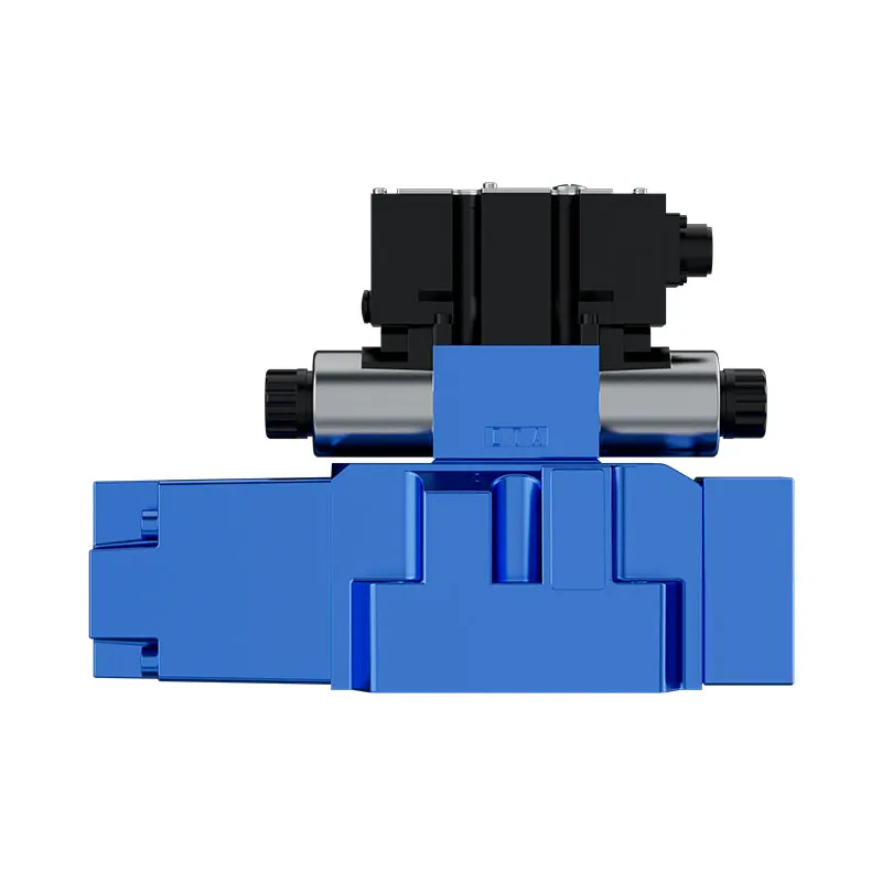
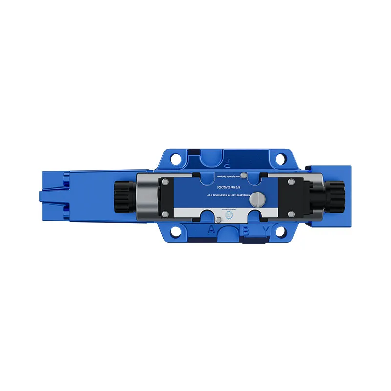
The Prance Pilot Proportional Valve for Press 4WRZE page provides a real valve reference for an application inquiry. Its original exterior photographs help identify the offered assembly. They cannot demonstrate internal metering-edge shape, cavitation resistance, permissible return pressure, or performance under the operating point described here. Request documentation for the complete ordered code.
For a quotation or replacement review, specify flow in each direction, pressure on all relevant ports, fluid and temperature range, commanded motion, load behavior, and the conditions where noise occurs. Include the existing valve identification and circuit. A general request for a quieter proportional valve lacks the information needed to assess compatibility.
Check control and installation requirements as well as nominal size. The correct spool function, pilot arrangement, signal interface, and mounting connections matter to the machine’s behavior. Do not infer these from a family name or substitute a visually similar valve without confirming the approved configuration.
Inspect damage and verify the correction safely
Depressurize, isolate stored energy, secure loads, and follow the manufacturer’s procedure before removal or internal inspection. Preserve the orientation and location of observed damage. Photographs should distinguish the affected surface from nearby deposits or scoring. Do not clean away evidence before the responsible inspection has documented it.
Erosion-like damage needs interpretation. Contamination, mechanical contact, corrosion, and cavitation can produce different patterns, but appearance alone is not a complete diagnosis. Relate the damage location to the actual flow direction and recorded operating condition. A replacement part may remove the immediate symptom while leaving the damaging circuit condition unchanged.
After an approved correction, repeat the comparable operating condition and check both the symptom and the machine function. Record noise behavior, pressure pair, temperature, actuator response, and any new effects on shared circuits. If the machine cannot be safely tested through the required condition, retain an explicit acceptance limitation rather than declaring the valve problem solved.
Frequently asked questions
Can a valve cavitate while both gauges show positive pressure?
Yes, local pressure inside a restriction can be lower than the pressures at external test points. Positive gauge readings do not exclude that possibility. A component-specific assessment still needs the fluid, temperature, geometry, flow, and pressure conditions.
Does a crackling sound prove cavitation?
No. Air in the oil, turbulence, unstable pressure control, and transmitted mechanical noise can produce similar symptoms. Use the sound to locate and characterize the event, then verify the hydraulic conditions before assigning a cause.
Is higher return pressure always safer for a noisy valve?
No. It may alter local conditions but can exceed return or drain limits, change actuator forces, or increase losses. Any modification requires a review of the full circuit and exact component limits rather than a trial restriction.
Will a larger valve necessarily solve the problem?
No. Size changes the operating opening and pressure-loss behavior, but the spool, control range, load dynamics, and pressure distribution still matter. A replacement must satisfy the required motion and stability as well as the noise concern.
Which information should be sent with a valve-noise inquiry?
Provide the full valve code, circuit drawing, flow and pressure at the event, fluid temperature, valve command, actuator direction, and any maintenance changes. Include a safely recorded sound or vibration timeline as supporting evidence, not as the sole diagnosis.
Related product and engineering resources
Pilot Proportional Valve for Press 4WRZE, hydraulic valve product range, How should system designers interpret hydraulic valve pressure drop?, Hydraulic Valve Power-Loss States: Spring Return, Detent, and Fail-Safe Review. Confirm the complete product code and application requirements when requesting a configuration review.
Technical references
- NPTEL IIT Guwahati: local pressure, cavitation, collapse, and bulk modulus
- ISA InTech: cavitation, flashing, and choked-flow distinctions
Further learning: hydraulic valves
5.2 – Directional Control Valves by NPTEL-NOC IITM provides background on valve functions. This NPTEL lesson explains the pump or valve fundamentals used here. It does not demonstrate the exact startup, steering, or cavitation test described in this article. It supplements the component fundamentals; it is not a test procedure for the complete circuit discussed above.