Wenzhou Prance Hydraulic Equipment Co., Ltd.

Drei-Wege-Reduzierungs-Entlastungsventile: Steuerung des Drucks aus beiden Richtungen
A hydraulic pressure reducing relieving valve controls a lower-pressure branch and provides a path for excess downstream pressure to escape. A reducing-only valve mainly restricts incoming supply; it cannot automatically be assumed to discharge pressure created by an external load or trapped-fluid heating. Choose the function from the complete circuit, including how pressure can rise after the supply passage closes. Confirm the exact valve symbol, port assignments, relieving capacity, and return-pressure limits. A small pilot drain is not automatically a full-flow relief connection, and a pressure-reducing function is not a substitute for every required safety or load-holding device.
Start with the downstream pressure source
A branch may need lower pressure than the main supply because it operates a clamp, pilot circuit, auxiliary actuator, or another component with a different requirement. A reducing valve senses the controlled downstream pressure and throttles supply as that pressure approaches its setting. This is different from a main relief valve that responds to pressure on its inlet side by diverting flow.
Now ask what happens after the reducing passage closes. An external force may push an actuator, another circuit may feed the branch through a connection, or trapped oil may warm. In those cases the source of the pressure increase is downstream of the closed supply path. Simply closing that path further cannot remove the trapped volume or release the added pressure. That is the operating situation a reducing/relieving arrangement is intended to address, within its documented capacity.
Follow the three functional states
Below the controlled pressure, the reducing path admits fluid from the high-pressure supply to the branch. Near the control point, the valve meters that incoming flow to balance demand and maintain the reduced pressure within its performance characteristics. If downstream pressure rises sufficiently above the regulating condition, a reducing/relieving design opens a separate path from the controlled branch toward the designated return port.
The transition is not an ideal switch at one mathematically exact pressure. Spring characteristics, spool overlap, hysteresis, flow forces, pilot arrangement, and operating flow can affect the actual pressure-flow response. Use the particular valve’s reducing and relieving curves. A label showing only the adjustment range does not establish the pressure that will occur during a high-flow relieving event.
For that reason, compare the expected downstream event with the relieving side of the documentation rather than checking only the normal supply rating. A valve capable of passing the required reducing flow does not necessarily have the same acceptable performance when fluid flows out of the branch. Port descriptions and performance curves must establish both duties.
Distinguish a drain from a working return
Some pressure controls use a drain to keep their spring chamber or pilot stage referenced to a specified pressure. That drain may carry only leakage or pilot flow. A reducing/relieving valve also needs a route capable of carrying the intended relieving flow. Depending on the design, functions may share a port or use separate passages. The symbol and manufacturer instructions establish the arrangement.
Do not connect an unverified small drain hose and assume it can discharge the full actuator flow. Restriction in the relieving return can raise downstream pressure and change the regulating behavior. Return back pressure may also change the pressure reference, depending on the valve design. Check maximum pressure, flow capacity, routing, and any required dedicated connection for each port separately.
Compare the functions before selecting a replacement
| Circuit requirement | Reducing-only function | Reducing/relieving function | Verifizierung erforderlich |
|---|---|---|---|
| Supply a lower-pressure branch | Meters incoming supply | Meters incoming supply | Required reducing flow and pressure-flow behavior |
| Handle pressure generated in the branch | Cannot be assumed to discharge it | Provides a documented relieving path | Cause, duration, and amount of relieving flow |
| Reference a pilot or spring chamber | May require a drain | May share or separate drain and return duties | Exact port diagram and back-pressure sensitivity |
| Reverse flow through the branch | Depends on the design | Also depends on the design | Check-valve options and reverse-flow limits |
| Prevent hazardous load movement | Not established by reducing alone | Not established by relieving alone | Separate machine risk review and load control |
| Replace an existing valve | Matching adjustment range is insufficient | Matching adjustment range is insufficient | Function, interfaces, capacity, and full ordering code |
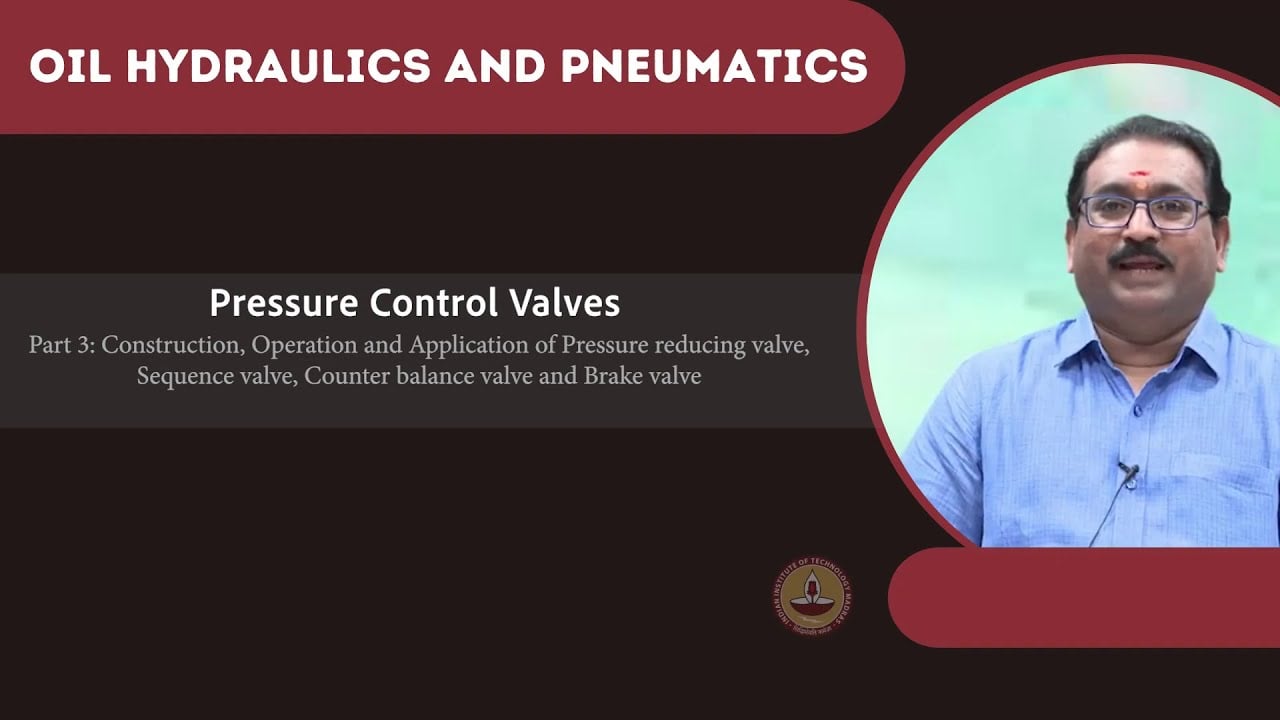
This is a qualitative selection table, not a product parameter sheet. The NPTEL pressure-control lessons distinguish downstream regulation from upstream pressure relief. Specific reducing/relieving behavior must be checked against the selected manufacturer’s technical information. None of these functions is assigned to a pictured directional valve merely because it belongs to the same hydraulic system.
Estimate the relieving duty from the physical event
If an actuator is being forced backward, the oil leaving its controlled chamber can be related to effective piston area and imposed velocity. That flow can be much larger than pilot leakage. Establish the actual chamber, motion direction, and any other flow path before estimating the required valve duty. Differential cylinder areas can produce pressure relationships that a simple pressure-setting comparison misses.
Thermal expansion of an isolated volume is a different duty from sustained actuator motion. It may involve little displaced volume but still create an unacceptable pressure rise if no suitable path exists. Do not size every event as a continuous full-flow event, and do not dismiss all events as minor thermal relief. Identify the credible cause first, then use its flow, duration, pressure, and temperature conditions for selection.
A main system relief upstream of a closed reducing valve does not necessarily protect the isolated downstream volume. Trace a continuous hydraulic path from the threatened volume to the protective device in every relevant valve position. If that path is blocked, the upstream device’s presence alone does not resolve the branch-pressure question.
Check the pressure reference under real return conditions
A return connection that looks satisfactory during idle operation can experience a pressure increase when another function sends flow through the same manifold or filter. If the pressure control references that return, the controlled branch may behave differently even though its adjustment screw has not moved. Record branch pressure and the relevant return or drain pressure during the same event.
Keep the distinction between gauge pressure and pressure difference clear. A spring-balanced mechanism responds to forces at its effective areas. The application documentation determines which pressure contributes to that balance. Do not apply a universal one-to-one correction to every valve, because internally balanced, externally drained, direct-acting, and pilot-operated arrangements can differ.
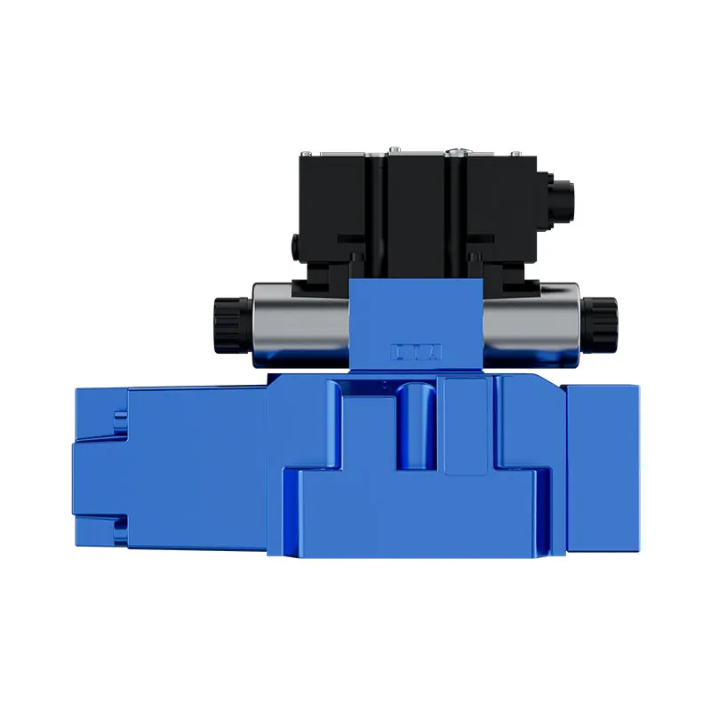
Relate the control to the actual Prance product
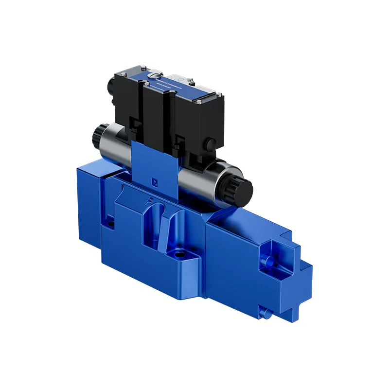
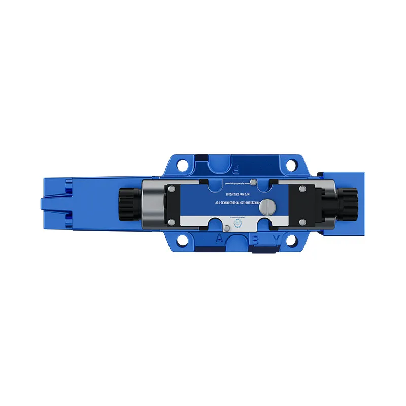
The website offers a Pilot Proportional Valve for Press 4WRZE. Its published description identifies a pilot-operated proportional directional-control product associated with controlling direction and flow. The original exterior photographs illustrate that product family in a broader hydraulic-control discussion. They do not show or prove that this valve contains a reducing/relieving stage.
A press circuit may require a separate branch-pressure control in addition to its directional valve. Determine that need from the circuit and the load, not from the appearance of the directional valve. For a quotation, identify which function is required from each component. Ask for the complete code, applicable hydraulic symbol, installation interface, and documentation establishing the exact pressure-control duty. Do not substitute a 4WRZE photograph or name for the missing specification of another valve.
Commission without masking the cause
Before adjustment, confirm port identity, line routing, fluid suitability, and the manufacturer-approved starting condition. Use the machine’s safe commissioning procedure and suitable instruments. Record supply pressure, controlled pressure, return pressure, temperature, flow state, and adjustment condition. Begin with the permitted test conditions rather than forcing an actuator against a stop to create an improvised pressure source.
If the branch pressure is too high, establish whether supply regulation is failing or downstream pressure is being generated independently. The two problems require different checks. Contamination, a restricted drain, wrong connection, unsuitable flow range, or an incorrect valve function may all require investigation. Turning the adjustment screw without identifying the operating state can conceal evidence and create an unsafe setting elsewhere in the cycle.
Decide what the purchase specification must contain
Specify the required reduced pressure under its defined flow condition, supply-pressure range, reducing flow, relieving flow and duration, fluid, temperature, and permitted return pressure. Include the downstream source of pressure, reverse-flow requirements, and the state required when electrical or hydraulic power is lost. State whether any setting is a factory test value or an installed acceptance requirement.
Request the reducing and relieving performance curves, port assignments, drain instructions, and any pilot-flow information needed for system design. Identify the cartridge cavity or mounting interface separately from the hydraulic function. A physically fitting valve can still behave differently. Where personnel safety or load restraint depends on pressure control, the machine designer must verify the protective architecture rather than relying on a generic catalog description.
The acceptance test should demonstrate normal regulation and the intended relieving behavior within approved conditions. Preserve the final settings and measurements. Isolate power, release stored hydraulic energy, and restrain potential movement before disturbing any connection; never use a loosened fitting as an informal pressure-relief method.
Häufig gestellte Fragen
Ist ein Druckminderventil dasselbe wie ein Druckbegrenzungsventil?
No. A reducing valve regulates the pressure downstream by controlling incoming supply. A relief valve responds to its inlet pressure by opening a discharge path. A reducing/relieving valve combines downstream regulation with a defined downstream discharge function.
Does every three-port reducing valve provide full relieving flow?
No. A third connection may be a pilot or spring-chamber drain. Read the hydraulic symbol, port descriptions, and performance data. Relieving flow and allowable return pressure must be documented rather than inferred from the number of connections.
Can a reducing/relieving valve hold a suspended load safely?
That cannot be concluded from its pressure-control function. Relieving can permit fluid to leave a loaded chamber. A suspended load needs a machine-specific review of load holding, stopping, failure response, and any required independent protective devices.
Why does branch pressure change when another function runs?
Shared return pressure, supply limitations, pilot interactions, or load changes may influence the branch. Measure the relevant pressures together and trace the actual flow paths. Do not assume the adjustment has drifted before checking circuit conditions.
Is the pictured 4WRZE a reducing/relieving valve?
The website identifies it as a pilot-operated proportional directional valve. Its photograph does not establish a reducing/relieving function. Select any separate pressure-control component from verified documentation and the complete circuit requirements.
Verwandte Produkt- und Ingenieurressourcen
Vorsteuer-Proportionalventil für Presse 4WRZE, Hydraulikventil-Produktpalette, Hydraulische Wegeventile: Wie sich Richtung, Druck und Durchfluss unterscheiden, Innen- vs. Außenventilablauf: Wie sich der Rückdruck im Tank auf die Steuerung auswirkt. Bestätigen Sie den vollständigen Produktcode und die Anwendungsanforderungen bei der Anforderung einer Konfigurationsüberprüfung.
Technische Referenzen
Universitätslektion: Hydraulikventile
5.8 – Druckregelventile von NPTEL-NOC IITM bieten Hintergrundinformationen zu den Betriebsprinzipien von Ventilen. Es ergänzt die Komponenten-Grundlagen; es ist kein Testverfahren für den oben diskutierten vollständigen Stromkreis.