Wenzhou Prance Hydraulic Equipment Co., Ltd.

Hydrostatic Neutral Creep: Separating Pump Offset from Load Effects
A closed loop hydraulic pump neutral creep complaint means the machine moves when the operator expects no drive command. It does not prove the pump needs adjustment. A biased input, a control that fails to return, an incorrect mechanical neutral, or an external load driving the transmission can produce similar observations. First secure the machine and identify whether the motion is powered creep or load-induced movement. Then compare command, control response and loop behavior using the exact machine service procedure. A neutral setting is neither a parking brake nor a substitute for a load-holding system.
Define the movement before choosing a repair
Describe what moves, in which direction, and under what conditions. A vehicle that inches forward on level ground at engine idle presents a different diagnostic problem from one that rolls downhill after the drive is disabled. An industrial drive that rotates with an unloaded shaft differs from a winch whose suspended load attempts to turn the motor. The word creep alone hides those distinctions.
For a repeatable complaint, record the operating mode, oil condition, engine speed and whether the operator control visibly returns to its rest position. Use observations already available from normal operation; do not recreate uncontrolled movement simply to collect data. Where motion cannot be safely contained under the manufacturer’s test arrangement, stop the machine and refer it for qualified service.
Also distinguish continued slow rotation from a brief movement during pressure decay. Both deserve investigation, but a finite relaxation event and a sustained drive can have different causes. A video captured from a safe position during an existing event may help a service team understand the symptom without placing anyone near moving components.
Separate commanded neutral from physical neutral
A centered joystick or released pedal is a human interface condition. It does not necessarily mean the pump receives the intended neutral signal. A linkage can bind before reaching its stop. An electrical command can remain biased even though the lever looks centered. A hydraulic control can receive a residual pilot signal. The control architecture determines which evidence matters.
Compare the requested command with the actual signal at the approved diagnostic point. For an electronic machine, that may involve both a controller status value and a measurement specified by the service documentation. A display reporting zero demand does not establish the current delivered to a control coil. Conversely, a measured current is not automatically abnormal because some control designs use a defined neutral command rather than no current.
Do not apply a universal neutral voltage, current or pilot-pressure value. Obtain the complete pump and control code and the machine manufacturer’s procedure. The Danfoss reference manual linked below illustrates separate checks for input faults and pump neutral on its own pump families. Its connector details, settings and service operations must not be transferred to a Prance AA4VG configuration.
Understand why a small offset can produce motion
A variable-displacement closed-circuit pump changes its delivery through displacement control. Near neutral, a small residual displacement can still create net flow. Whether that flow produces visible movement depends on motor displacement, leakage, mechanical resistance, gearing and the external load. This is why the same input bias may be obvious on an unloaded drive and hidden under a heavier opposing load.
As a teaching example, suppose a hypothetical pump retains 0.4 cubic centimeters per revolution of effective displacement at 1,200 rpm. Ideal delivery is 0.48 liters per minute. If all of that delivery reached a hypothetical 80 cubic centimeter motor, ideal motor speed would be 6 rpm. This calculation ignores leakage, compressibility, friction and any gearing; it is not a prediction for an AA4VG pump or a safe-motion threshold.
The example explains why adjusting a controller’s displayed zero without checking the actual drive can leave the complaint unresolved. It also explains why a low-speed test needs a defined acceptance criterion. A pump can be close to neutral yet still fail the machine’s required stationary condition. The machine designer must specify how neutral, braking and motion prevention work together.
Use a diagnostic sequence that preserves the evidence
Start with the approved inspection of the operator controls, return mechanism and visible wiring or pilot connections. Look for an obstruction, damaged mounting, changed cable routing, loose connector or recent replacement. Record what changed before the complaint began. A newly installed control handle or repaired harness can be more relevant than the age of the rotating group.
Next establish whether the external command meets the specified neutral condition. A qualified technician may then use the manufacturer’s controlled isolation test to distinguish an external input fault from an internal control or mechanical-neutral problem. This article does not provide a generic disconnect-and-run procedure: removing a signal can change brake logic, enable logic or the control’s fail state.
If the external signal is correct, follow the pump-specific sequence for control neutral and mechanical neutral. Those are separate service concepts on some designs. Do not turn an exposed screw merely because another pump manual calls it a neutral adjustment. A similar-looking feature may serve a different function or require a special test fixture and pressure measurement arrangement.
Interpret pressure observations with the load in mind
Loop-pressure information can help explain the direction of power transfer, but a pressure difference is not a standalone proof of pump bias. An external load can drive the motor and create pressure. A brake applying or releasing can change the pressure pattern. Charge pressure and control supply can affect the control’s ability to achieve its intended state.
Compare observations only at the specified test points and with the documented load condition. Main-loop ports, servo ports, charge ports and case connections serve different purposes. Never substitute one because the fitting is convenient. Connecting gauges, opening lines and removing components require isolation, stored-energy control and the exact service procedure.
| Beobachtung unter einem genehmigten Test | Possible direction of investigation | Evidence needed before adjustment |
|---|---|---|
| Neutral demand changes when the lever is lightly returned | Linkage, return mechanism or input calibration | Specified rest position and actual signal |
| Correct interface demand but biased signal at pump | Controller output, wiring or pilot circuit | Signal measured at approved diagnostic point |
| Correct external input, persistent powered motion | Control neutral, mechanical neutral or internal fault | Pump-specific test sequence and loop conditions |
| Motion follows slope or suspended load with drive inactive | Brake, load holding or external back-driving | Machine brake function and load-restraint assessment |
| Behavior changes only as oil warms | Clearance, leakage or control response sensitivity | Comparable temperatures, speed and command conditions |
This table is a diagnostic aid rather than a fault-code chart. Several causes can coexist, and each conclusion needs the machine’s approved verification method.
Distinguish drift under load from powered creep
A hydraulic transmission is an energy-transfer system. When a load supplies energy to the motor shaft, the direction of power transfer can reverse. Leakage and circuit features then influence how well the hydraulic loop resists motion. That situation must be assessed together with the machine’s brakes and holding devices.
A pump-neutral adjustment cannot certify the parking function of a mobile machine or the holding function of a lifting system. Likewise, a successful stationary test on level ground does not demonstrate secure holding on a slope. Treat reports of unexpected movement as a machine-level issue until the responsible system has been identified.
Do not remove a load, disable a brake or bypass an interlock as an informal way of separating the causes. Where the manufacturer provides a service test, use its specified supports, restraints, personnel clearance and operating conditions. If those arrangements are unavailable, the appropriate next action is controlled service access rather than improvised diagnosis.
Check the actual control configuration before replacement
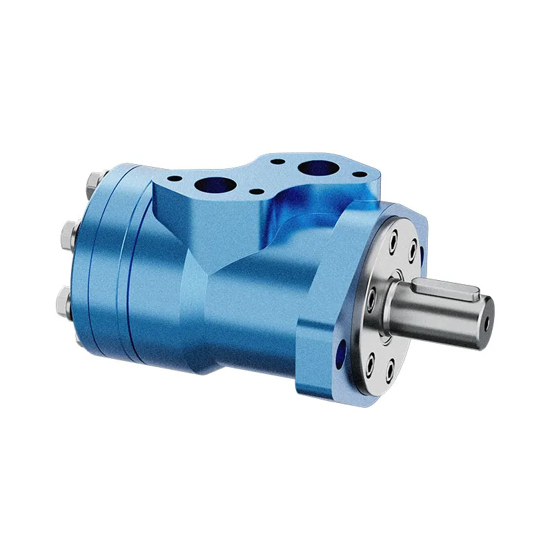
The website’s AA4VG product entry identifies a closed-loop variable-displacement pump family. The original photographs below help identify the exterior and the broad component category. They do not establish the installed control code, internal neutral setting, connector assignment or compatibility with an existing machine controller.
For replacement evaluation, compare the full order code, displacement, direction of rotation, mounting, shaft, ports and control version. Ask how neutral command, enable logic and braking coordination are specified. A physically mountable pump can still have a different control response. Do not describe a replacement as interchangeable solely because it belongs to a familiar family.
Send clear nameplate photographs and the machine schematic with an enquiry. State whether the complaint appeared before or after a pump, controller or linkage replacement. That information helps distinguish an application mismatch from wear or service adjustment. Keep reference-family manuals clearly separated from the documents approved for the offered product.

Verify the repair across the conditions that exposed the fault
After an authorized repair, repeat the manufacturer’s acceptance tests with the documented restraints and clearance. Confirm neutral entry from both directions, return behavior and the specified temperature range. A result obtained only after manually nudging the lever into place is not evidence of reliable automatic return.
Record the original symptom, confirmed cause, changed component or setting, and final measured result. Include the exact documentation revision used. If the behavior remains intermittent, preserve that uncertainty rather than declaring the pump repaired after one successful attempt. Unexpected movement that cannot be reproduced safely still needs a defined service disposition.
For procurement, the useful deliverable is a confirmed control and installation specification together with an acceptance method. Request that review before ordering parts to address a creep complaint. It reduces the chance of replacing a pump while leaving a biased command, brake defect or load-driven movement unresolved.

Häufig gestellte Fragen
Does neutral creep always mean the pump is worn?
No. External command bias, linkage return, control-neutral errors and machine load effects can resemble internal wear. Identify the source of motion before selecting a replacement or an adjustment.
Can I use the neutral adjustment from another pump manual?
No. Similar pump families can use different controls, test ports and procedures. Use the documentation for the exact pump and machine configuration; reference manuals explain principles without authorizing a service operation.
Why does creep change when the oil warms?
Oil condition changes leakage, drag and control behavior. Temperature sensitivity helps define the test conditions but does not by itself identify a failed component. Compare like-for-like observations within the approved operating range.
Is zero loop-pressure difference proof of safe parking?
No. A pressure reading at one moment is not a brake or holding-system acceptance test. Parking and load restraint require the machine designer’s specified systems and verification.
What should I provide for a pump enquiry?
Provide the complete pump and control codes, machine application, schematic, input-signal specification and a precise description of the movement. Include the verified test findings rather than requesting a pump based only on the word creep.
Verwandte Produkt- und Ingenieurressourcen
Geschlossene Verstell-Kolbenpumpe AA4VG, Hydraulikpumpen-Produktpalette, Auswahlleitfaden für Axialkolbenverstellpumpen im geschlossenen Kreis, Hydraulikmotor-Spülventil: Geschlossener Kreislauf-Kühlung erklärt. Bestätigen Sie den vollständigen Produktcode und die Anwendungsanforderungen bei der Anforderung einer Konfigurationsüberprüfung.
Technische Referenzen
- NPTEL: basic concept of hydrostatic transmission
- Danfoss closed-circuit pump service manual: neutral troubleshooting; reference family only
- NIOSH: inspection of hazardous-energy control procedures
Weiterführendes Lernen: Hydraulikpumpen
mod-22 lec-23 Basic Concept of Hydrostatic Transmission (HST) System by nptelhrd provides background on pump operating principles. This lesson explains pump-to-motor energy transfer in hydrostatic transmissions; neutral adjustment and braking require the exact machine service procedure. It supplements the component fundamentals; it is not a test procedure for the complete circuit discussed above.