Wenzhou Prance Hydraulic Equipment Co., Ltd.

Hydraulic Motor Flushing Valve: Closed-Loop Cooling Explained
A hydraulic motor flushing valve removes a controlled amount of oil from an approved circuit path so replacement oil can help manage temperature and contamination. In many closed-loop arrangements, a shuttle selects the low-pressure side and a flushing element controls the exchange path. The exact design, flow and pressure conditions are configuration-specific. Flushing is not the same function as case drainage, relief protection or anti-cavitation replenishment.
This guide explains how to review a motor flushing arrangement and its effect on the charge-flow and cooling budget. It does not specify a universal flushing flow or authorize adding a valve to an unreviewed circuit.
Start with the reason for exchanging oil
A closed-loop circuit recirculates much of its working oil between pump and motor. Exchanging some oil through an approved path can support cooling and fluid management. The exchanged oil must be replaced, typically through the designed charge or replenishment system. The benefit depends on the complete heat-removal and make-up arrangement.
State whether the objective is temperature management, oil exchange or a specific manufacturer requirement. A flushing valve does not repair excessive mechanical friction or an incorrectly loaded motor. If the machine overheats, identify where power is being lost before assuming that a larger flushing flow is the correct solution.
Trace the selected low-pressure path
A shuttle arrangement can select the lower-pressure working line as rotation and load conditions change. Read the exact symbol and assembly drawing. The labels on a valve block are not sufficient to establish which internal passage connects to the flushing outlet in every operating state.
Check reversal, neutral and load-driven operation. The working line that is low during ordinary motoring can change when the load drives the motor. The arrangement must preserve suitable pressure and filling conditions throughout the approved duty. Do not assume that a line is permanently the return because it connects to one side of the motor.
Distinguish the flow functions
Internal leakage is an inherent flow through the motor's internal clearances. Case drainage removes housing leakage and any flow specifically routed through the housing. Flushing deliberately exchanges oil through a defined path. Make-up supplies a working line that needs replenishment. Relief protection limits pressure through a different function.
Several functions may share a block or affect the same charge-flow budget, but they should be listed separately. A drain-flow reading can include both leakage and flushing in some configurations. Without that distinction, an operator may diagnose normal intentional flow as wear or select an undersized drain line.
Establish the charge-flow balance
The source replacing exchanged oil must also cover the other circuit demands defined by the design. Leakage, control flow and replenishment can consume part of the available supply. Increasing flushing flow without checking the balance can reduce the margin needed to maintain suitable circuit pressure and filling.
Review the demanding combinations of speed, pressure, temperature and simultaneous control actions. A charge pump's nominal flow does not necessarily equal the useful flow available at the actual operating condition. Use supplier data and a documented circuit calculation rather than subtracting unrelated catalog maxima without considering when they occur.
Review the flushing element's characteristics
The assembly may use an orifice, pressure-controlled element or another specified design. Obtain the exact configuration and the applicable flow-versus-pressure information. Flow can vary with pressure difference and fluid properties. A nominal flow label should not be interpreted as constant flow under every machine condition.
Identify the pressure setting, destination pressure and any adjustment procedure. If the element is factory-set, do not alter it without authorization from the component or system instructions. Record cartridge markings and block revision so future maintenance can distinguish a changed configuration from a malfunction of the original arrangement.
Include the drain and cooling destination
Trace where the flushed oil goes. It may pass through a housing or a separate approved path depending on design. Check case-pressure limits, destination pressure and line losses. If flow is routed through the motor case, the drain route must handle the combined flow without exceeding the applicable housing conditions.
Review cooler and reservoir connections as part of the complete thermal path. Removing hot oil from a working loop is not equivalent to rejecting the heat to the environment. If the cooler is restricted or undersized for the duty, more exchange flow may not solve the temperature problem. Keep circuit exchange and heat rejection as separate calculations.
Compare the main review items
| Prüfungselement | Information required | Practical question |
|---|---|---|
| Zweck | Thermal duty and reason for exchange | Does flushing address the actual source of overheating? |
| Selection path | Shuttle and block schematic | Is the intended low-pressure line selected in each state? |
| Exchange flow | Element characteristics and fluid conditions | What flow occurs at the real operating point? |
| Charge balance | Supply, leakage, control and replenishment demands | Can replacement oil maintain the required conditions? |
| Destination | Case, drain, cooler and tank route | Does the route remain within pressure and thermal limits? |
| Maintenance identity | Cartridge code, setting and block revision | Can the installed configuration be verified after service? |
The table identifies system checks. It does not imply that one standard flushing cartridge is suitable for all motors or closed-loop circuits.
Evaluate cold and hot conditions separately
Cold oil can increase resistance in the flushing and drain paths, while warmer oil can change leakage and the available charge-flow margin. The condition causing high pressure loss can differ from the condition causing insufficient replacement flow. Evaluate both rather than labeling one temperature universally worst case.
Record temperature at meaningful circuit locations. A housing surface reading is useful context but does not replace oil temperature in the loop or drain. Compare the measurement with operating pressure, speed and command. A temperature report without the associated duty cannot establish whether a changed flushing arrangement improved the machine.
Diagnose a suspected flushing problem
Symptoms may include unexpected temperature rise, altered charge pressure or a drain-flow change. First establish the installed configuration and whether the relevant operating state changed. Compare measured flow with the element's specified behavior and confirm the destination path. A faulty shuttle, restricted passage or wrong cartridge can require different remedies.
Keep the original settings documented and avoid changing several valves at once. If the fault appears only in one rotation direction, inspect the selected paths and relevant pressure differences. If it follows a maintenance event, verify part markings, orientation and contamination controls before assuming the motor has developed excessive leakage.
Separate wear from intentional flow
When interpreting a motor drain test, identify any flushing contribution and the test procedure's conditions. A high reading that includes deliberate exchange cannot be compared directly with a leakage-only limit. The supplier should state what the accepted figure includes for the selected configuration.
Use synchronized work pressures, speed, temperature and flow. If a service procedure isolates a flushing contribution, follow it exactly and preserve the required pressure and lubrication conditions. Do not block an unfamiliar line merely to make the flow measurement look smaller. A measurement made by altering the circuit improperly can be misleading and harmful.
Validate a change with the whole circuit
If an approved design change alters flushing flow or its destination, recalculate the charge balance and check drain and cooler conditions. Review whether braking, replenishment or control behavior changes. A modification to one integrated block can affect several functions even when only the flushing cartridge was intended to change.
Commission through the relevant duty in both directions where applicable. Record loop and charge pressures, motor speed, oil temperatures and exchanged flow using a suitable setup. Compare stable and transition conditions with the acceptance plan. Treat reduced temperature as one result, not proof that every pressure and filling requirement remains satisfied.
Plan maintenance without adding unnecessary adjustments
Identify the inspection points, permitted service actions and replacement parts in the documentation. Contamination can affect small passages or moving elements, but cleaning must follow the component instructions. Do not introduce abrasives or debris while trying to clear a restriction. Preserve removed parts when a failure investigation is required.
Keep a configuration log for cartridges, settings and valve blocks. An undocumented substitute can create a different flow characteristic while retaining the same external housing. Future troubleshooting should begin with verified identity rather than assuming the block still contains its original components.
Information to include in a flushing-valve RFQ
Provide the motor and pump codes, closed-loop schematic, operating speeds, pressure conditions and thermal duty. State charge-source capability, other demands, fluid and temperature range, drain route and cooler arrangement. Identify whether exchanged oil passes through the motor case and whether a block integrates other protective functions.
Request the exact assembly drawing, selection-path description, flow characteristics and operating limits. Ask what is included in the motor's drain-flow data and which tests validate the proposed arrangement. The quotation should describe a defined circuit match rather than offering a flushing flow number without its conditions.
Häufig gestellte Fragen
Is a flushing valve the same as an anti-cavitation valve?
No. Flushing exchanges oil through a designed path; anti-cavitation replenishment supplies a line that needs make-up flow. Both can affect the available charge supply and must be reviewed together.
Does more flushing always improve cooling?
No. The charge-flow balance, destination pressure and heat-rejection system can limit the benefit. First identify the source of heat and check the complete circuit.
Can drain flow include flushing flow?
Yes, in configurations that route exchange oil through the housing or drain path. Confirm the definition before comparing the reading with a leakage-only value.
Why can a flushing issue appear in only one direction?
The selected low-pressure path changes with operating state. Check the shuttle, connections, pressure differences and cartridge identity in both directions.
What should be checked after changing a flushing cartridge?
Verify the exact part and configuration, exchanged flow, charge pressure, drain pressure and temperatures under the actual duty. Check transitions as well as steady operation.
Produktdaten und entsprechende technische Ressourcen
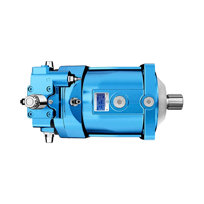
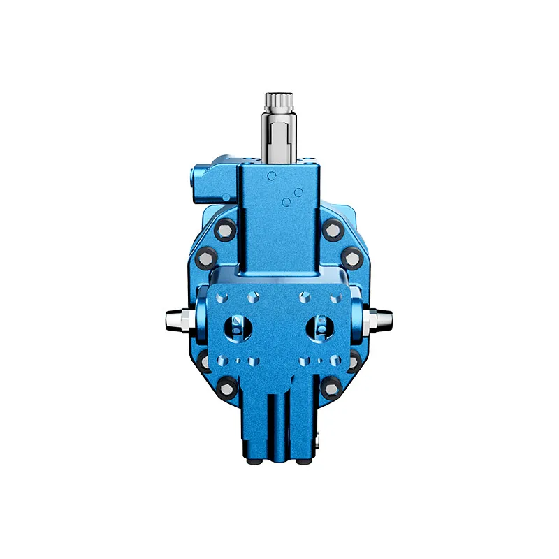
Für eine Anfrage zu einem bestimmten Produkt, bitte überprüfen Sie Hydraulischer Hochdruck-Kolbenmotor A6VM und die vollständige Spezifikation und Installationsbedingungen zu liefern. Bereich der Kolbenmotoren, Bereich der Orbitalmotoren, Motorkasten-Druckkontrollen, Motorabfluss-Durchflussmessung, Berechnung der Motorleistung, Maßangaben und Anschlussregeln für die Hydraulikmotorgehäuse-Entlüftungsleitung, Orbit Motor Internal Leakage: Wear Points and Diagnostic Tests. Die Produktfotos veranschaulichen die Katalogkonfigurationen; sie geben jedoch keine Druck-, Geschwindigkeits- oder Wellenlastwerte für eine nicht bestätigte Bestellung an.
Lehrveranstaltung an der Universität: Grundlagen des hydraulischen Motors
NPTEL-NOC IITM stellt eine Lehre über den hydraulischen Motor aus dem Institut für Technik und Ingenieurwissenschaften in Madras vor. Die Vorlesung unterstützt die Unterscheidung zwischen hydraulischem Eingangs- und Abtrieb, wie in dieser Anleitung beschrieben. Die spezifischen Installationseinstellungen und Betriebsgrenzen des jeweiligen Bauteils erfordern weiterhin die Dokumentation des ausgewählten Motors.
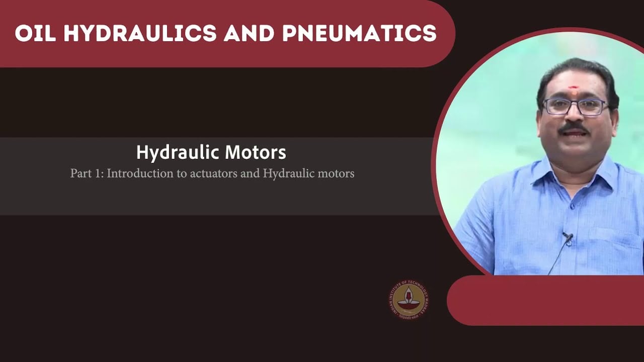
Öffnen Sie die NPTEL-Vorlesung zu Hydraulikmotoren.
Technische und Sicherheitsreferenzen
- NPTEL: Grundlagen der industriellen Ölhydraulik und Pneumatik
- NIOSH: Verletzungen durch gefährliche Energie verhindern
- Technische Referenz: Prinzipien des Betriebes von Orbitalmotoren und Installation
Diese Referenzen liefern ein pädagogisches und technisches Kontext. Die spezifischen Bewertungen für bestimmte Modelle von Referenzherstellern sind keine Spezifikationen für ein Prance-Produkt und implizieren keine Zugehörigkeit oder Genehmigung der jeweiligen Marke.