Wenzhou Prance Hydraulic Equipment Co., Ltd.

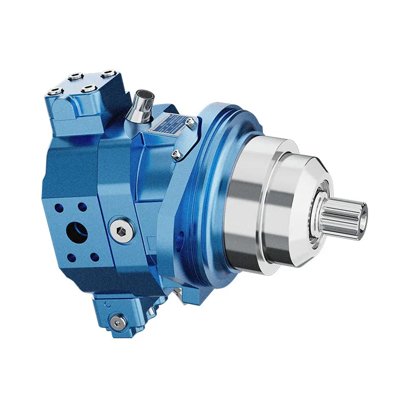
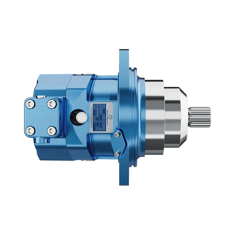
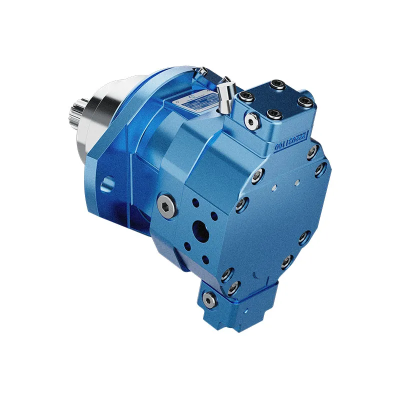
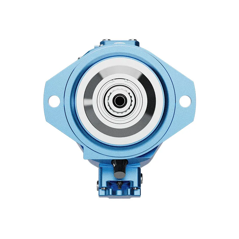
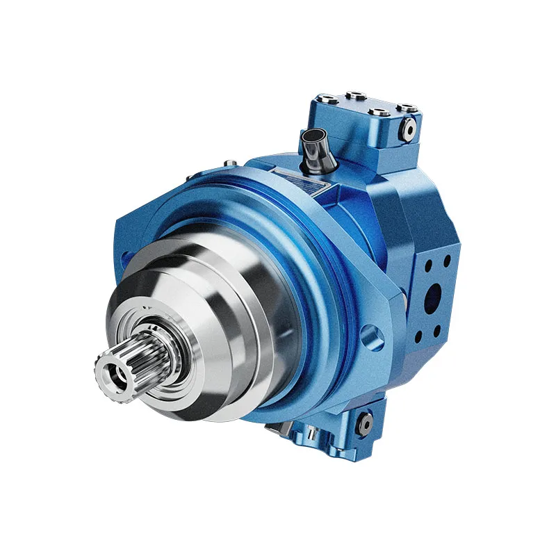
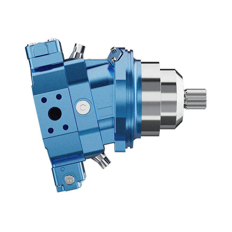
Hydraulic Bent Fixed Displacement Piston Motor A6VE
1.Robust motor with long service life .
2.Approved for very high rotational speeds
3.High control range (can be swiveled to zero)
4.Variety of contra Is Optionally with flushing and boost-pressure valve mounted
5.Optionally with Integrated or mounted counterbalance valve
6.Bent-axis design
Detaillierte Beschreibung
This hydraulic pump is equipped with a robust motor, which is constructed with high-strength materials and optimized structural design to resist wear, impact and high-temperature effects, ensuring a long service life even in harsh working environments such as mobile machinery and industrial stations, reducing maintenance costs and downtime. The motor is approved for very high rotational speeds, enabling stable and reliable operation at extreme high-speed conditions without excessive vibration, noise or component damage, which is essential for high-efficiency hydraulic drive systems requiring rapid power transmission. It boasts a high control range and can be swiveled to zero displacement, allowing flexible adjustment of output flow from maximum to zero, realizing precise control of the hydraulic system and avoiding energy waste caused by redundant flow. It offers a variety of control options to meet different system control needs, and can be optionally equipped with a mounted flushing and boost-pressure valve to enhance oil cleanliness and maintain stable boost pressure, improving system reliability. Additionally, it can be optionally configured with an integrated or mounted counterbalance valve to prevent load drift and ensure safe and stable operation of the system. Adopting a bent-axis design, it optimizes power transmission efficiency, reduces internal mechanical wear, and maintains a compact structure while enhancing overall operational stability.
Auswahl und Preisanfrage
This motor series should be selected from the required torque, speed and duty cycle. Confirm displacement, working pressure, case-drain arrangement where applicable, mounting interface and fluid conditions before final selection.
Angaben für Ihre Angebotsanfrage
- Required torque and speed at working pressure
- Preferred displacement or calculated displacement
- Mounting flange, shaft and port orientation
- Duty cycle, fluid, temperature and operating environment
Verwandte Ressourcen
Code eingeben
Axialkolbeneinheit
| 01 | Bent-axis design, variable | A6V |
Betriebsart
| 02 | Plug-in motor | E |
Größe (NG)
| 03 | Geometric displacement, see "Technical data" | 28 | 250 |
Control device
| 28 | 250 | |||||
| 04 | Proportionalregelung, hydraulisch | ΔPst=10 bar | ● | ● | HD1 | |
| ΔPst=25 bar | ● | ● | HD2 | |||
| Proportionalregelung, elektrisch | U=12V | ● | ● | EP1 | ||
| U=24V | ● | ● | EP2 | |||
| Two-point control hydraulisch |
- | ● | HZ | |||
| ● | - | HZ1 | ||||
| Two-point control elektrisch |
U=12V | ● | ● | EZ1 | ||
| U=24V | ● | ● | EZ2 | |||
| Automatic control high-pressure-dependent |
with minimum pressure increase | ΔP≤approx. 10 bar | ● | ● | HA1 | |
| with pressure increase | ΔP=100 bar | ● | ● | HA2 | ||
| Automatische Steuerung, drehzahlabhängig | Pst/PHD = 3/100, hydraulic travel direction valve | - | ● | DA | ||
| Pst/PHD = 5/100, electric travel direction valve + electric Vgmax switching | U=12V | ● | - | DA3 | ||
Pressure control (only for HD and EP)
| 28 and250 | ||||
| 05 | Without pressure control/override | ● | ● | |
| Pressure control, fixed setting | ● | ● | D | |
Pressure control/override
| 28 and250 | ||||
| 06 | Without pressure control/override | ● | ● | |
| Override of the HA1 and HA2 controls, hydraulic remote controlled, proportional | ● | ● | T | |
Serie
| 07 | Series 6, index 3 | 63 |
Drehrichtung
| 08 | Viewed on drive shaft, bidirectional | W |
Setting range for displacement1)
| 28 | 250 | |||
| 09 | Vg-Moll =0 to 0.7 VG-Max(without code) | ● | - | |
| Vg-Moll =0 to 0.4 VG-Max VG-Max = VG-Max to 0.8 VG-Max | - | ● | 1 | |
| Vg-Moll > 0.4 VG-Max to 0.8 VG-Max VG-Max = VG-Max to 0.8 VG-Max | - | ● | 2 | |
Dichtungsmaterial
| 28 | 250 | |||
| 10 | FKM(fluoroelastomer) shaft seal | ● | ● | V |
Antriebswelle
| 28 | 250 | |||
| 11 | Splined shaft DIN 5480 | ● | - | A |
| - | ● | Z | ||
•=Available ○=On request -=Not available  =Preferred program
1) Please specify exact settings for Vgmin und VGMax in plain text when ordering: Vgmin = ... cm3, VGMax = ... cm3
Montageflansch
| 28 | 250 | ||||
| 12 | Similar to ISO 3019-2 | 2-Loch | ● | - | L |
| 4-Loch | - | ● | M | ||
Funktionierender Port2)
| 28 | 250 | |||||
| 13 | SAE working ports A and B at side, opposite | 02 | 0 | ● | ● | 020 |
| 7 | ● | ● | 027 | |||
| Port plate for mounting a counterbalance valve, with 1-stage pressure relief valve (pilot operated)3) | 38 | 0 | - | ●4) | 380 | |
Valves
| 14 | Without | 0 |
| Flushing and boost-pressure valve, mounted | 7 | |
| Mounted counterbalance valve | 8 |
Speed sensor
| 28 | 250 | |||
| 15 | Without speed sensor | ● | ● | 0 |
| Prepared for DSA speed sensor | ○ | ● | U | |
| DSA speed sensor angebaut5) | ○ | ● | V | |
Magnetstecker6)
| 28 | 250 | |||
| 16 | Without connector (without solenoid, only for hydraulic control) (Size 250 without code) |
● | - | 0 |
| - | ● | |||
| DEUTSCH - molded connector, 2-pin, without suppressor diode | ● | - | P | |
| HIRSCHMANN connector - without suppressor diode (without code) | - | ● | ||
Beginn der Steuerung
| 28 | 250 | ||||
| 17 | Port plate 02, 38 | at Vgmin (standard for HA) | ● | ● | A |
| at VGMax(standard for HD, HZ, EP, EZ, DA) | ● | ● | B | ||
Standard/ special version
| 18 | Standard version (without symbol) | |
| Standard version with installation variants, e.g. T ports open or closed, contrary to standard | -Y | |
| Special version | -S |
•=Available ○=On request -=Not available =Preferred program
Notice
▶Note the project planning notes on page 34!
▶In addition to the type code, please specify the relevant technical data when placing your order.
▶Please note that not all type code combinations are available although the individual functions are marked as being available.
2) Fastening thread, metric.
3) Only possible in combination with HD, EP and HA control
4) Counterbalance valve MHB32, please contact us.
5) Specify the type code separately for sensor in accordance with data sheet 95133 (DSA) and observe the requirements for the electronics.
6) Connectors for other electric components may deviate.
Technische Daten
| Größe | NG | 28 | 250 | ||
| Geometric displacement, per revolution1) | VGMax | cm3 | 28.1 | 250 | |
| Vgmin | cm3 | 0 | 0 | ||
| Vgx | cm3 | 18 | 205 | ||
| Maximale Drehzahl2) (in compliance with maximum permissible inlet flow) |
at VG-Max | nnom | U/min | 5550 | 2700 |
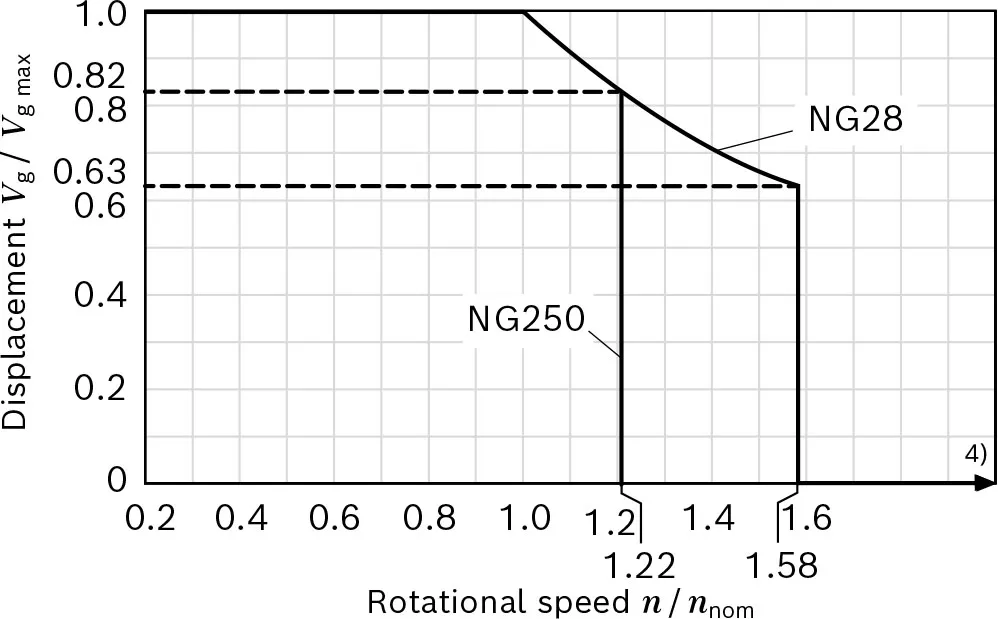
| at Vg < Vgx (see diagram) | nMax | U/min | 8750 | 3300 | |
| at Vg 0 | nMax | U/min | 10450 | 3300 | |
| Inlet flow | at nnom und VG-Max | qv max | l/min | 156 | 675 |
| Drehmoment3) | at VG-Max and ΔP ▪ 400 bar | M | Machs gut | 179 | – |
| at VG-Max and ΔP ▪ 350 bar | M | Machs gut | 157 | 1391 | |
| Rotary stiffness | VG-Max to Vg/2 | Cmin | kNm/rad | 6 | 60 |
| Vg/2 to 0 (interpolated) | Cmin | kNm/rad | 18 | 181 | |
| Moment of inertia of the rotary group | JTw | kgm2 | 0.0014 | 0,061 | |
| Fallzahl | V | l | 0.5 | 3.0 | |
| Weight approx. | with port plate 02, 38 | m | kg | 16 | 1105) |
▼Permissible displacement depending on the rotational speed
Determination of the characteristics
| Determination of the characteristics | ||
| Inlet flow | qv=(Vg×n)/(1000×ηv) | l/min |
| Drehzahl | n=(qv×1000×ŋv)/Vg | U/min |
| Drehmoment | M=(Vg×Δp×ŋhm)/(20×π) | Machs gut |
| Macht | P=(2π×M×n)/60000=(qv×Δp×ŋt)/600 | kW |
Schlüssel
| Vg | Displacement per revolution [cm3] |
| Δp | ]Differential pressure [bar] |
| n | Rotational speed [rpm] |
| ŋv | Volumetrischer Wirkungsgrad |
| ŋhm | Hydraulisch-mechanischer Wirkungsgrad |
| ŋt | Total efficiency (t = 7v x 7hm) |
Notice
▶Theoretical values, without efficiency and tolerances;values rounded
▶Operation above the maximum values or below the minimum values may result in a loss of function,a reduced service life or in the destruction of the axial piston unit. Other permissible limit values, such as speed variation, reduced angular acceleration as a function of the frequency and the permissible angular acceleration at start (lower than the maximum angular acceleration) can be found in data sheet 90261.
1) The minimum and maximum displacement can be steplessly varied,see Ordering code on page 2. (Standard setting size 250 if not Specified when ordering: Vgmin = 0.2×Vg Max, Vg Max = Vg Max).
2) The values are applicable:
- for the optimum viscosity range from νentscheiden = 36 bis 16 mm2/s
- with hydraulic fluid based on mineral oils
3)Torque without radial force, with radial force see page 8
4)Values in this range on request
5)Port plate 02
Permissible radial and axial loading on the drive shafts
| Größe | NG | 28 | 250 | ||
| Antriebswelle | W30 | W50 | |||
| Maximum radial force1) at distance a (to the shaft collar) | 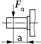 |
FQ-max | N | 4838 | 12002) |
| a | mm | 17.5 | 41 | ||
| Maximum torque at FQ-max | TQ-max | Machs gut | 179 | 3) | |
| Maximum differential pressure at VGMax und Fqmax | ΔpQ-max | bar | 400 | 3) | |
| Maximum axial force,at standstill orpressure-free operation | 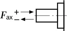 |
+ FAch, Max | N | 0 | 0 |
| - FAch, Max | N | 315 | 1200 | ||
| Permissible axial force per bar working pressure | + Fax perm/bar | N/bar | 4.6 | 3) | |
Effect of radial force Fq on bearing service life
By selecting a suitable direction of radial force Fq, the load on the bearings, caused by the internal rotary group forces can be reduced, thus optimizing the bearing service life.Recommended position of mating gear is dependent on the direction of rotation. Examples:
▼Gear output drive
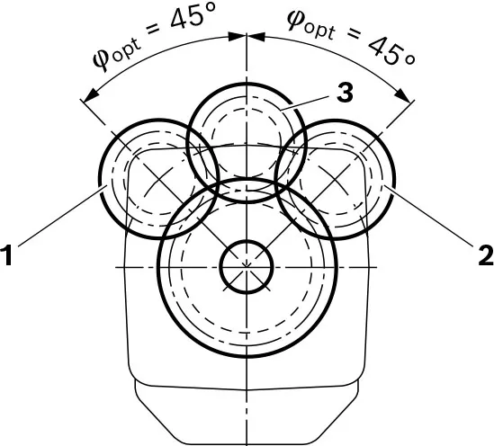
1 "Counter-clockwise" rotational direction, pressure at port B
2 "Clockwise" rotational direction, pressure at port A
3 Bidirectional direction of rotation
Notice
▶The values given are maximum values and do not apply
to continuous operation.
▶The permissible axial force in direction -Fax is to be avoided as the bearing service life is reduced.
▶Special requirements apply in the case of belt output drives. Please contact us.
1)With intermittent operation
2)When at standstill or when axial piston unit working in depressurized conditions. Higher forces are permissible under pressure, please contact us.
3) Please contact us.