Wenzhou Prance Hydraulic Equipment Co., Ltd.

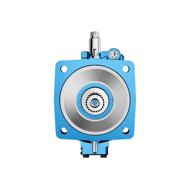
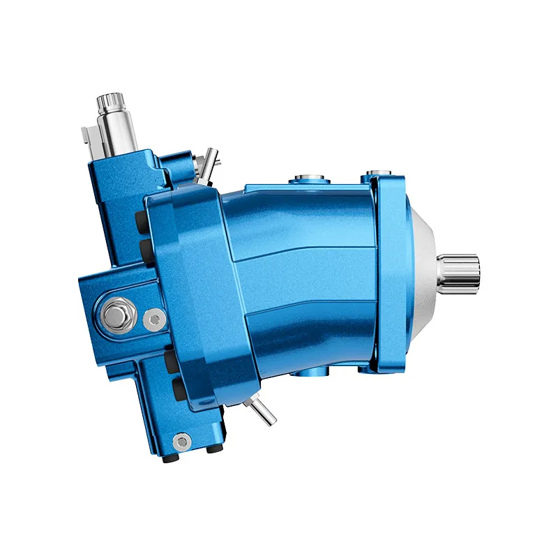
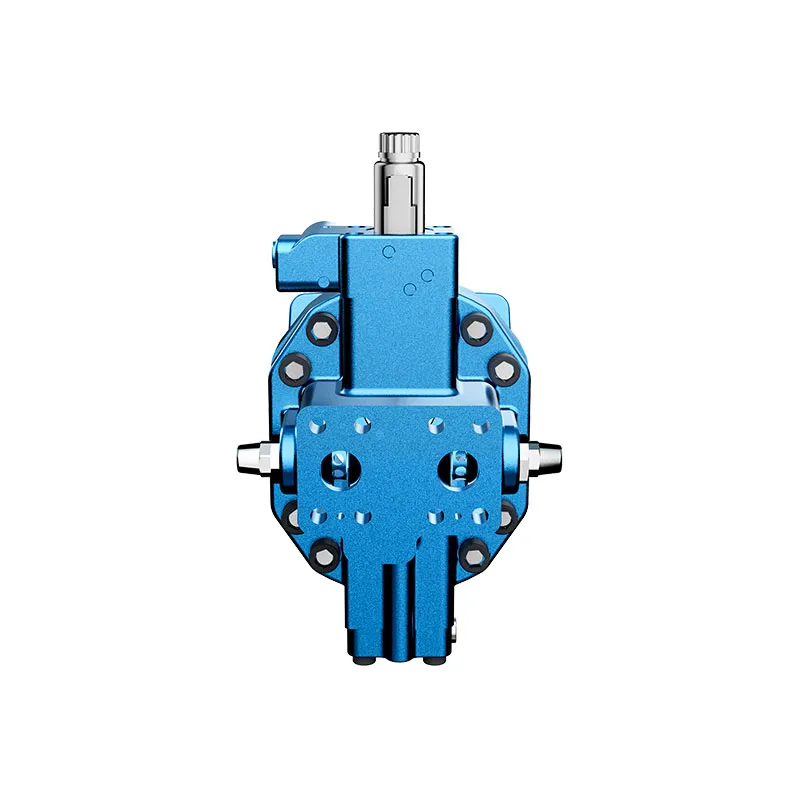
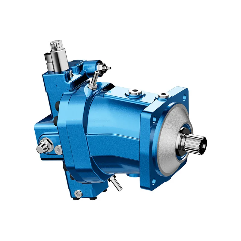
A6VM Variable Displacement Bent Axis Motor
The A6VM variable displacement bent-axis motor is selected around the required torque-speed envelope and control behavior. Its available displacement settings can cover different operating points, but each setting remains subject to pressure, speed and duty limits.
- Verstellbarer Bent-Achsen-Motor
- Multiple displacement-control arrangements
- Flushing and boost valve options
- Counterbalance configuration must be specified
PRANCE HYDRAULIC · PRODUCT SERIES
A6VM Variable Displacement Bent Axis Motor
Axial piston; bent axis, variable displacement · Confirm open or closed circuit configuration
The A6VM variable displacement bent-axis motor is selected around the required torque-speed envelope and control behavior. Its available displacement settings can cover different operating points, but each setting remains subject to pressure, speed and duty limits.
Model
✓
Request a QuotationTechnische Daten & Datenblatt anzeigenA6VMAxial piston; bent axis, variable displacement
Confirm the complete model and approved specification with Prance Hydraulic. Product-series references alone do not establish interchangeability.
Configuration review · Technical documentation · Product selection
Produktdetails
- Verstellbarer Bent-Achsen-Motor
- Multiple displacement-control arrangements
- Flushing and boost valve options
- Counterbalance configuration must be specified
CATEGORIES: Kolbenmotor, Verstellbarer Kolbenmotor
A6VM Features & Application
Verstellbarer Bent-Achsen-Motor
Specify the displacement range or switching arrangement and verify performance at each required setting.
Multiple displacement-control arrangements
Match the complete control option and its command requirements to the existing controller. Similar housings can use different control arrangements.
Flushing and boost valve options
Account for pilot or replenishment demand and the relevant pressure limits. Include filtration and the return or drain route in the circuit review.
Counterbalance configuration must be specified
Specify the full MS order code, installation drawing and operating duty so the quotation can identify the proposed configuration.
A6VM Specifications
| Series / model | A6VM |
|---|---|
| Product type | A6VM Variable Displacement Bent Axis Motor |
| Design | Axial piston; bent axis, variable displacement |
| Circuit / selection | Confirm open or closed circuit configuration |
| Published technical-table sizes | 28, 55, 80, 107, 140 and 160 |
| Displacement and control | Match size and control to the exact offered configuration |
A6VM Selection & Configuration
The A6VM variable displacement bent-axis motor is selected around the required torque-speed envelope and control behavior. Its available displacement settings can cover different operating points, but each setting remains subject to pressure, speed and duty limits.
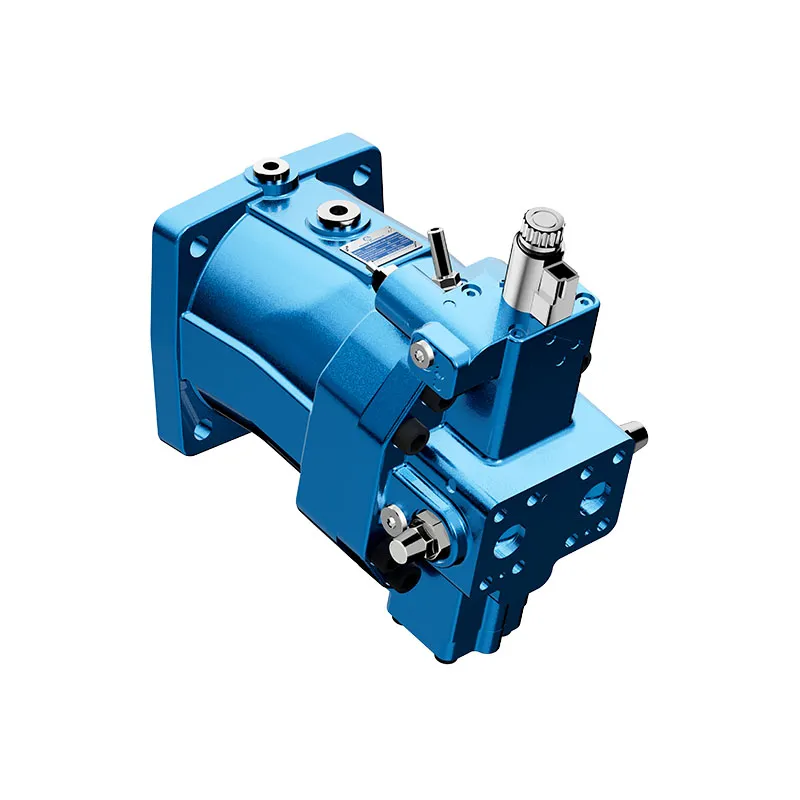
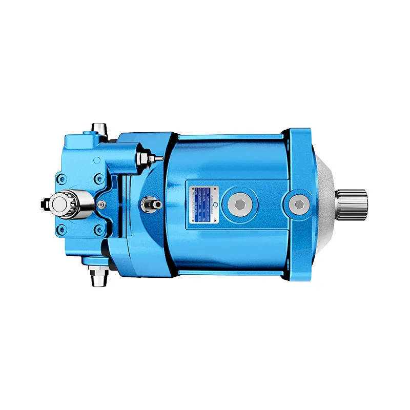
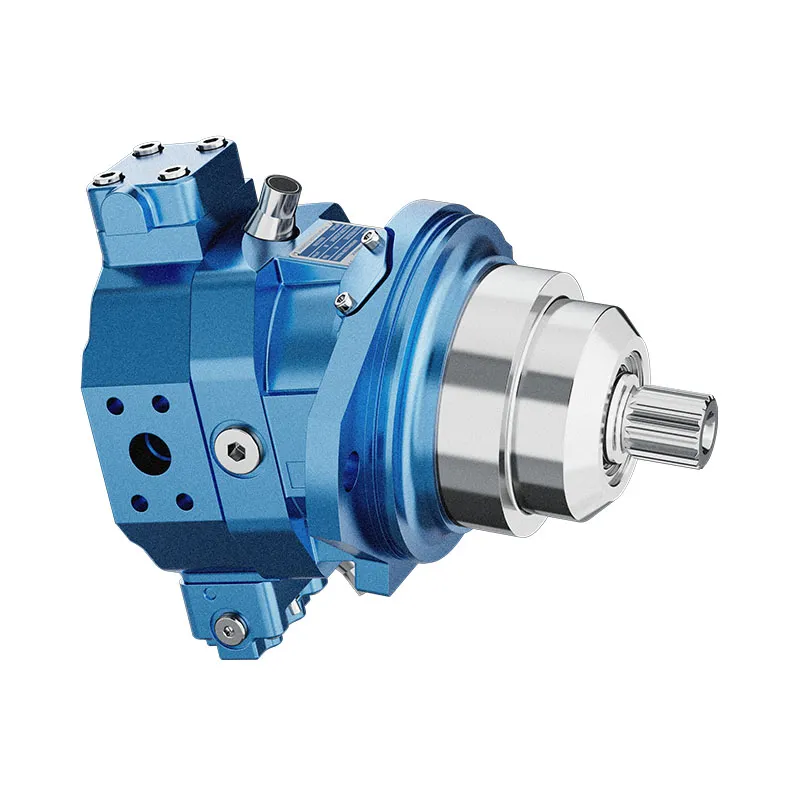
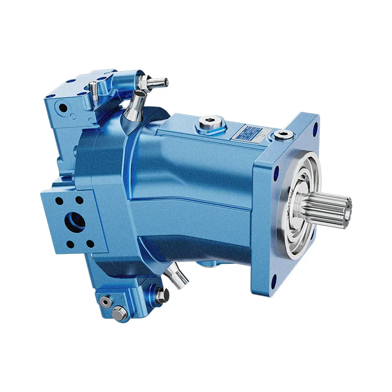
Compare starting, continuous and high-speed duty separately. Provide the control type and desired displacement on loss of command or pilot pressure. Confirm whether flushing, boost or counterbalance components are included rather than inferring them from the product photograph.
cURL Too many subrequests by single Worker invocation. To configure this limit, refer to https://developers.cloudflare.com/workers/wrangler/configuration/#limits.
cURL Too many subrequests by single Worker invocation. To configure this limit, refer to https://developers.cloudflare.com/workers/wrangler/configuration/#limits.
Hydraulic pumps · Hydraulic motors · Hydraulic valves
Send the MS nameplate, operating requirements and installation drawing for a configuration review before quoting.
- Model review — send the full model code or an existing nameplate photograph.
- Interface matching — confirm shaft, mounting flange, rotation and ports.
- Operating conditions — provide flow, pressure, speed, fluid and duty cycle.
- Documentation — request the relevant product data and drawings for your review.

A6VM Buying Guide
Use this sequence to prepare the A6VM configuration for review and quotation.
- Define starting and continuous torque, speed range and duty cycle.
- Specify available flow, work-port pressure difference and return pressure.
- Confirm the displacement setting and required behavior during starting and stopping.
- Check shaft, mounting pilot, flange, port orientation and external loads.
- Review case drainage, replenishment and any displacement control.
- Specify fluid conditions and any independent braking requirement.
- Approve the complete model, operating envelope, drawing and quantity.
Selection, Documentation & Project Support

Selection Support
Learn more →Share your hydraulic circuit, operating point and installation requirements for a configuration discussion.
Flow · Pressure · Speed · Interfaces

Technical Resources
Learn more →Review product documentation, model codes and technical data before finalizing the specification.
Datasheets · Model codes · Drawings

Project Inquiries
Learn more →Send your required model, quantity, application and project requirements to discuss your inquiry.
Product inquiries · Configuration review
Configuration, Quantity & Delivery
Confirm the complete MS code, approved drawing and operating limits. Availability, quantity, documentation and delivery date are confirmed in the quotation.
Discuss Your A6VM Application
Send the full model code, operating duty, installation details and quantity.
Request a A6VM QuotationA6VM Questions Before Ordering
What type of product is the A6VM?
AA6VM Variable Displacement Bent Axis Motor. Design: Axial piston; bent axis, variable displacement. Confirm open or closed circuit configuration. Confirm the complete order code for the offered version.
Can a similar motor replace the A6VM?
cURL Too many subrequests by single Worker invocation. To configure this limit, refer to https://developers.cloudflare.com/workers/wrangler/configuration/#limits.
cURL Too many subrequests by single Worker invocation. To configure this limit, refer to https://developers.cloudflare.com/workers/wrangler/configuration/#limits
cURL Too many subrequests by single Worker invocation. To configure this limit, refer to https://developers.cloudflare.com/workers/wrangler/configuration/#limits.
A6VM Technical Data & Documents
View A6VM catalog data and operating conditions
cURL Too many subrequests by single Worker invocation. To configure this limit, refer to https://developers.cloudflare.com/workers/wrangler/configuration/#limits.
Technische Daten
| Größe | NG | 28 | 55 | 80 | 107 | 140 | 160 | ||
| Geometrisches Fördervolumen, pro Umdrehung1) | VGMax | cm3 | 28.1 | 54.8 | 80 | 107 | 140 | 160 | |
| VGemeinde | cm3 | 0 | 0 | 0 | 0 | 0 | 0 | ||
| Vgx | cm3 | 18 | 35 | 51 | 68 | 88 | 61 | ||
| Maximale Drehzahl2)(unter Einhaltung des maximal zulässigen Einlassstroms) | bei VGMax | nnom | U/min | 5550 | 4450 | 3900 | 3550 | 3250 | 3100 |
| bei Vg<Vgx | nMax | U/min | 8750 | 7000 | 6150 | 5600 | 5150 | 4900 | |
| wo VLos | nMax | U/min | 10450 | 8350 | 7350 | 6300 | 5750 | 5500 | |
| Einlassströmung3) | bei nnom und VGMax | qVmax | l/min | 156 | 244 | 312 | 380 | 455 | 496 |
| Drehmoment4) | bei VGMax und Δp = 400 bar | T | Machs gut | 179 | 349 | 509 | 681 | 891 | 1019 |
| bei VGMax und Δp = 350 bar | T | Machs gut | 157 | 305 | 446 | 596 | 778 | 891 | |
| Verdrehsteifigkeit | VGMax zu Vg/2 | cmin. | kNm/rad | 6 | 10 | 16 | 21 | 34 | 35 |
| Vg/2 bis 0 (interpoliert) | cmin. | kNm/rad | 18 | 32 | 48 | 65 | 93 | 105 | |
| Trägheitsmoment der Drehgruppe | JTW | kgm2 | 0.0014 | 0.0042 | 0.008 | 0.127 | 0.0207 | 0.0253 | |
| Maximale Winkelbeschleunigung | α | rad/s2 | 47000 | 31500 | 24000 | 19000 | 11000 | 11000 | |
| Fallzahl | V | l | 0.5 | 0.75 | 1.2 | 1.5 | 1.8 | 2.4 | |
| Gewicht ca. | m | kg | 16 | 28 | 36 | 46 | 61 | 62 | |
| Größe | NG | 200 | 250 | 355 | 500 | 1000 | ||
| Geometrisches Fördervolumen, pro Umdrehung1) | VGMax | cm3 | 200 | 250 | 355 | 500 | 1000 | |
| VGemeinde | cm3 | 0 | 0 | 0 | 0 | 0 | ||
| Vgx | cm3 | 76 | 205 | 300 | 417 | 1000 | ||
| Maximale Drehzahl2)(unter Einhaltung des maximal zulässigen Einlassstroms) | bei VGMax | nnom | U/min | 2900 | 2700 | 2240 | 2000 | 1600 |
| bei Vg<Vgx | nMax | U/min | 4600 | 3300 | 2650 | 2400 | 1600 | |
| wo VLos | nMax | U/min | 5100 | 3300 | 2650 | 2400 | 1600 | |
| Einlassströmung3) | bei nnom und VGMax | qVmax | l/min | 580 | 675 | 795 | 1000 | 1600 |
| Drehmoment4) | bei VGMax und Δp = 400 bar | T | Machs gut | 1273 | - | - | - | - |
| bei VGMax und Δp = 350 bar | T | Machs gut | 1114 | 1391 | 1978 | 2785 | 5571 | |
| Verdrehsteifigkeit | VGMax zu Vg/2 | cmin. | kNm/rad | 44 | 60 | 75 | 115 | 281 |
| Vg/2 bis 0 (interpoliert) | cmin. | kNm/rad | 130 | 181 | 262 | 391 | 820 | |
| Trägheitsmoment der Drehgruppe | JTW | kgm2 | 0.0353 | 0.061 | 0.102 | 0.178 | 0.55 | |
| Maximale Winkelbeschleunigung | α | rad/s2 | 11000 | 10000 | 8300 | 5500 | 4000 | |
| Fallzahl | V | l | 2.7 | 3.00 | 5.0 | 7.0 | 16.0 | |
| Gewicht ca. | m | kg | 78 | 100 | 170 | 210 | 430 | |
Geschwindigkeitsbereich
Die Mindestdrehzahl nmin. is not restricted. Please consult us regarding applications requiring uniformity of the rotatory motion at low speeds. 1)The minimum and maximum displacement can be steplessly adjusted,(standard setting for sizes 250 to 1000 if ordering code is missing.Vgmin. = 0,2 × VgMax, VG-Max = VgMax) 2) The values are applicable: -for the optimum viscosity range from Ventscheiden= 36 bis 16 mm2/s -with hydraulic fluid based on mineral oils 3)Observe limitation of displacement due to counterbalance valve 4) Torque without radial force, with radial force.Hinweis
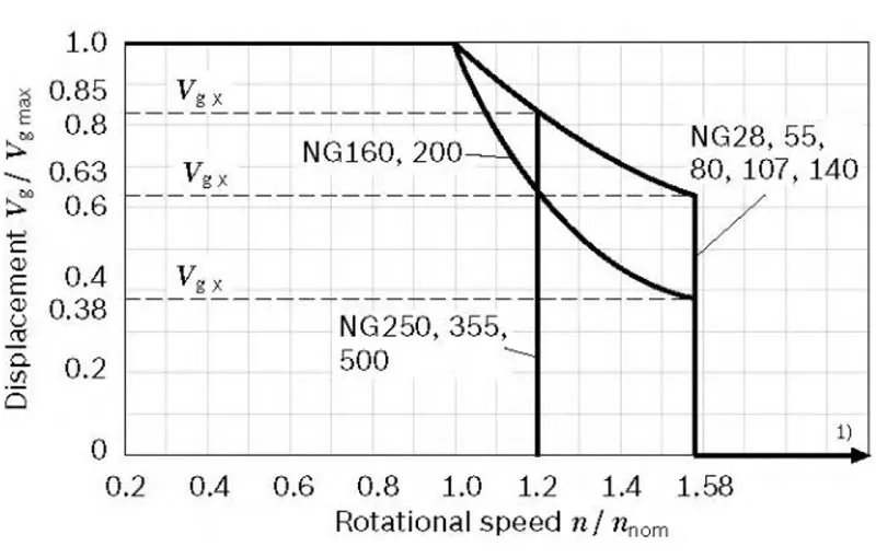
▶Theoretical values, without efficiency and tolerances;values rounded ▶Operation above the maximum values or below the minimum Values may result in a loss of function, a reducd service life or in the destruction of the axial piston unit. Other permissible limit values, such as speed variation, reduced angular acceleration as a function of the frequency and the permissible angular acceleration at start (lower than the maximum angular acceleration) can be found in data sheet 90261.▼Zulässige Verschiebung in Abhängigkeit von der Drehzahl
| Bestimmung der Betriebskennlinien | ||
| Einlassströmung | qv=(Vg×n)/(1000×ηv) | [U/min] |
| Drehzahl | n=(qv×1000×ηv)/Vg | U/min |
| Drehmoment | T=(Vg×Δp×ηhm)/(20×π) | [Nm] |
| Macht | P=(2π×T×n)/60000=(qv×Δp×ηt)/600 | [kW] |
Schlüssel
Vg= Verdrängung pro Umdrehung [cm3] Δp=Differential pressure [bar] n=Rotational speed [rpm] ηv=Volumetric efficiency ηhm=Hydraulic-mechanical efficiency ηt= Gesamtwirkungsgrad (ηt=nv × nhm)Watch A6VM Product Video
Related Selection Resources
Request a A6VM Quotation
Tell us your required configuration, quantity and application.
Ähnliche Produkte
Compare related hydraulic motors and confirm the complete configuration for your application.

Code eingeben
| 01 | 02 | 03 | 04 | 05 | 06 | 07 | 08 | 09 | 10 | 11 | 12 | 13 | 14 | 15 | 16 | 17 | 18 | 19 | 20 | |||
| A6V | M | / | 63 | W | - | V | - |
Hydraulikflüssigkeit
| 01 | Mineralöl und HFD. HFD für die Baugrößen 250 bis 1000 nur in Verbindung mit Langzeitlager "L" (ohne Kennbuchstabe) | ||
| HFB-, HFC-Flüssigkeit | Größe 28 bis 200 (ohne Code) | ||
| Größen 250 bis 1000 (nur in Verbindung mit Long-Life-Lagern "L") | E | ||
Axialkolbeneinheit
| 02 | Schrägaxelbauweise, verstellbar | A6V |
Kardanwellenlager
| 28...200 | 250 | 355 | 500 | 1000 | |||
| 03 | Standardlager (ohne Kennzeichnung) | ● | ● | ● | ● | - | |
| Langlebige Lager | - | ● | ● | ● | ● | L |
Betriebsart
| 04 | Motor (Einsteckmotor A6VE, siehe Datenblatt 91606) | M |
Größe (NG)
| 05 | Geometrische Verschiebung | 28 | 55 | 80 | 107 | 140 | 160 | 200 | 250 | 355 | 500 | 1000 |
Steuergerät1)
| 06 | Proportionalregelung, hydraulisch | ΔpSt. = 10 bar | ● | ● | ● | ● | ● | ● | ● | ● | ● | ● | ● | HD1 | |
| ΔpSt. = 25 bar | ● | ● | ● | ● | ● | ● | ● | ● | ● | ● | ● | HD2 | |||
| ΔpSt. = 35 bar | - | - | - | - | - | - | - | ● | ● | ● | ● | HD3 | |||
| Proportionalregelung, elektrisch | U=12V | ● | ● | ● | ● | ● | ● | ● | ● | ● | ● | ● | EP1 | ||
| U=24V | ● | ● | ● | ● | ● | ● | ● | ● | ● | ● | ● | EP2 | |||
| Zweipunktregelung, hydraulisch | - | - | - | - | - | - | - | ● | ● | ● | ● | HZ | |||
| ● | - | - | - | ● | ● | ● | - | - | - | - | HZ1 | ||||
| - | ● | ● | ● | - | - | - | - | - | - | - | HZ3 | ||||
| Zweipunktregelung, elektrisch | U=12V | ● | - | - | - | ● | ● | ● | ● | ● | ● | ● | EZ1 | ||
| U=24V | ● | - | - | - | ● | ● | ● | ● | ● | ● | ● | EZ2 | |||
| U=12V | - | ● | ● | ● | - | - | - | - | - | - | - | EZ3 | |||
| U=24V | - | ● | ● | ● | - | - | - | - | - | - | - | EZ4 | |||
| Automatische Steuerung,
im Zusammenhang mit Hochdruck |
Mit minimalem Druckanstieg
Δp≤ca. 10 bar Bei einer Druckerhöhung von Δp = 100 bar |
● | ● | ● | ● | ● | ● | ● | ● | ● | ● | ● | HA1 | ||
| ● | ● | ● | ● | ● | ● | ● | ● | ● | ● | ● | HA2 | ||||
| Automatische Steuerung, drehzahlabhängig
pst/pHD=3/100 Hydraulisches Wegeventil |
- | - | - | - | - | - | - | ● | ● | ● | ○ | DA | |||
| pst/pHD=5/100 | Hydraulisches Wegeventil | ● | ● | ● | ● | ● | ● | ● | - | - | - | - | DA1 | ||
| Elektrisches Wegeventil
Elektro-Vg Max Schaltkreis |
U=12V | ● | ● | ● | ● | ● | ● | ● | - | - | - | - | DA2 | ||
| U=24V | ● | ● | ● | ● | ● | ● | ● | - | - | - | - | DA3 | |||
| pst/pHD=8/100 | Hydraulisches Wegeventil | ● | ● | ● | ● | ● | ● | ● | - | - | - | - | DA4 | ||
| Elektrisches Wegeventil
Elektro-Vg Max Schaltkreis |
U=12V | ● | ● | ● | ● | ● | ● | ● | - | - | - | - | DA5 | ||
| U=24V | ● | ● | ● | ● | ● | ● | ● | - | - | - | - | DA6 | |||
| 28 | 55 | 80 | 107 | 140 | 160 | 200 | 250 | 355 | 500 | 1000 | ||||
| 07 | Ohne Druckregelung / Übersteuerung | ● | ● | ● | ● | ● | ● | ● | ● | ● | ● | ● | ||
| Druckregelung | fester Wert | ● | ● | ● | ● | ● | ● | ● | ● | ● | ● | ● | D | |
| Hydraulische Handbetätigung, Zweipunkt | ● | ● | ● | ● | ● | ● | ● | 2) | 2) | 2) | 2) | E | ||
| Hydraulische Fernbedienung, proportional | - | - | - | - | - | - | - | ● | ● | ● | ● | G | ||
• = Verfügbar ○ = Auf Anfrage - = Nicht verfügbar
1) Ansprechzeitdämpfung bei Bestellung angeben (Baugrößen 28 bis 200)
2) 2. Druckstufe bei Version D (Größen 250 bis 1000) serienmäßig eingebaut
Überschreibungen für die HA1- und HA2-Steuerungen
| 28 | 55 | 80 | 107 | 140 | 160 | 200 | 250 | 355 | 500 | 1000 | ||||
| 08 | Ohne Überschreibung (ohne Code) | ● | ● | ● | ● | ● | ● | ● | ● | ● | ● | ● | ||
| Hydraulische Handbetätigung, Fernsteuerung, proportional | ● | ● | ● | ● | ● | ● | ● | ● | ● | ● | ● | T | ||
| Fernbedienung elektrische Notbetätigung, zweipunkt | U=12V | ● | ● | ● | ● | ● | ● | ● | - | - | - | - | U1 | |
| U=24V | ● | ● | ● | ● | ● | ● | ● | - | - | - | - | U2 | ||
| Elektrische Übersteuerung | U=12V | ● | ● | ● | ● | ● | ● | ● | - | - | - | - | R1 | |
| Wegeventil, elektrisch | U=24V | ● | ● | ● | ● | ● | ● | ● | - | - | - | - | R2 | |
Serie
| 09 | Serie 6, Index 3 | 63 |
Drehrichtung
| 10 | Auf Antriebswelle betrachtet, in beide Richtungen | W |
Einstellung von Verdrängungsbereichen3)
| 28 | 55 | 80 | 107 | 140 | 160 | 200 | 250 | 355 | 500 | 1000 | |||
| 11 | VGemeinde = 0 bis 0,7 VGMax | ● | ● | ● | ● | ● | ● | ● | - | - | - | - | |
| VGemeinde = 0 bis 0,4 VGMax VGMax =VGMax auf 0,8 VGMax | - | - | - | - | - | - | - | ● | ● | ● | ● | 1 | |
| VGemeinde 0,4 VGMax auf 0,8 VGMax VGMax =VGMax auf 0,8 VGMax | - | - | - | - | - | - | - | ● | ● | ● | ● | 2 | |
Dichtungsmaterial
| 12 | FKM (Fluorelastomer) | V |
Antriebswelle
| 28 | 55 | 80 | 107 | 140 | 160 | 200 | 250 | 355 | 500 | 1000 | |||
| 13 | Passverzahnte Welle DIN 5480 | ● | ● | ● | ● | ● | ● | ● | - | - | - | - | A |
| ● | ● | ● | ● | ● | ● | - | ● | ● | ● | ● | Z | ||
| Welle mit Passfeder DIN 6885 | - | - | - | - | - | - | - | ● | ● | ● | ● | P | |
Montageflansch
| 28 | 55 | 80 | 107 | 140 | 160 | 200 | 250 | 355 | 500 | 1000 | |||
| 14 | ISO 3019-2 | 4-Loch | ● | ● | ● | ● | ● | ● | ● | ● | - | - | - |
| 8-Loch | - | - | - | - | - | - | - | - | ● | ● | ● | ||
Anschlussplatte für Arbeitsleitung4)
| 28 | 55 | 80 | 107 | 140 | 160 | 200 | 250 | 355 | 500 | 1000 | ||||||
| 15 | SAE-Arbeitsanschlüsse A und B hinten | 01 | 0 | ● | ● | ● | ● | ● | ● | ● | ● | ● | ● | ● | 010 | |
| 7 | ● | ● | ● | ● | ● | ● | ● | ● | ● | ● | ● | 017 | ||||
| SAE-Arbeitsanschlüsse A und B seitlich, gegenüberliegend | 02 | 0 | ● | ● | ● | ● | ● | ● | ● | ● | ● | ● | ● | 020 | ||
| 7 | ● | ● | ● | ● | ● | ● | ● | ● | ● | ● | ● | 027 | ||||
| SAE-Arbeitsanschlüsse A und B seitlich, gegenüberliegend + hinten | 15 | 0 | - | - | - | - | - | - | - | ● | ● | ● | ● | 150 | ||
| Anschlussplatte mit 1-Stufen-Druckbegrenzungsventilen zur Anbau von Senkbremsventilen5) | für BVD20 | 37 | 0 | - | - | - | ● | - | - | - | - | - | - | - | 370 | |
| 8 | - | - | - | ● | - | - | - | - | - | - | - | 378 | ||||
| für BVD20/BVD25 | 38 | 0 | - | ● | ● | ● | ● | ● | ● | ●6) | - | - | - | 380 | ||
| 8 | - | ● | ● | ● | ● | ● | ● | ●6) | - | - | - | 388 | ||||
| für BVE | 38 | 0 | - | - | - | ● | ● | ● | ● | - | - | - | - | 380 | ||
| 8 | - | - | - | ● | ● | ● | ● | - | - | - | - | 388 | ||||
0=Ohne Ventil
7=Spül- und Ladedruckventil, montiert
8=Sperrblock angebaut7)
• = Verfügbar ○ = Auf Anfrage - = Nicht verfügbar
3) Bitte geben Sie die genauen Einstellungen für V anGemeinde und VGMax im Klartext bei der Bestellung: VGemeinde=...cm3,VGMax=...cm3
4) Befestigungsgewinde, metrisch
5) Nur in Verbindung mit HD-, EP- und HA-Steuerung möglich.
6) Typcode für Senkbremsventil zur separaten Angebotserstellung gemäß Datenblatt 95522- BVD oder 95525-BVE.
7) Rohrbruchsicherung MHB32, bitte kontaktieren Sie uns.
Geschwindigkeitssensor
| 28 | 55 | 80 | 107 | 140 | 160 | 200 | 250 | 355 | 500 | 10008) | |||
| 16 | Ohne Geschwindigkeitssensor (ohne Code) | ● | ● | ● | ● | ● | ● | ● | ● | ● | ● | ● | O |
| Vorbereitet für Festplatten-geschwindigkeitssensor | ▲ | ▲ | ▲ | ▲ | ▲ | ▲ | ▲ | ● | ● | ● | - | F | |
| Festplattengeschwindigkeitssensor montiert9) | ▲ | ▲ | ▲ | ▲ | ▲ | ▲ | ▲ | ● | ● | ● | - | H | |
| Vorbereitet für DSM/DSA-Geschwindigkeitssensor | ● | ● | ● | ● | ● | ● | ● | - | - | - | - | U | |
| DSM/DSA-Geschwindigkeitssensor montiert9) | ● | ● | ● | ● | ● | ● | ● | - | - | - | - | V | |
Schwenk-Winkelsensor
| 28 | 55 | 80 | 107 | 140 | 160 | 200 | 250 | 355 | 500 | 1000 | |||
| 17 | Ohne Schwenkwinkelsensor | ● | ● | ● | ● | ● | ● | ● | ● | ● | ● | - | |
| Optischer Schwenkwinkelsensor | - | - | - | - | - | - | - | ● | ● | ● | ● | V | |
| Elektrischer Schwenkwinkelsensor | - | - | - | - | - | - | - | ● | ● | ● | ● | E | |
Magnetstecker
| 28 bis 200 | 250 bis 1000 | |||
| 18 | Ohne Stecker (ohne Magneten, nur mit hydraulischer Ansteuerung) (Größen 250 bis 1000) | ● | - | O |
| - | ● | |||
| DEUTSCH Steckverbinder, 2-polig – ohne Löschdiode | ● | - | P | |
| HIRSCHMANN-Stecker-ohne Entstördiode | - | ● | ||
Beginn der Steuerung
| 28 | 55 | 80 | 107 | 140 | 160 | 200 | 250 | 355 | 500 | 1000 | |||
| 19 | Um VGemeinde (Standard für HA) | ● | ● | ● | ● | ● | ● | ● | ● | ● | ● | ● | A |
| Bei VGMax(Standard für HD, HZ, EP, EZ, DA) | ● | ● | ● | ● | ● | ● | ● | ● | ● | ● | ● | B | |
Standard-/Spezialversion
| 20 | Standardversion | |
| Standardversion mit Installationsvarianten, z. B. T-Böhrung offen und geschlossen abweichend vom Standard | -Y | |
| Sonderversion | -S |
•=Verfügbar ○= Auf Anfrage ▲=Nicht für Neuprojekte - =Nicht verfügbar
Hinweis
▶Bitte geben Sie bei Ihrer Bestellung neben dem Typencode auch die relevanten technischen Daten an.
8) Bitte kontaktieren Sie uns.
9) Typenschlüssel für Sensor gemäß Datenblatt 95132-DSM oder 95133-DSA, 95135-HDD separat angeben und die Anforderungen an die Elektronik beachten.
Technische Daten
| Größe | NG | 28 | 55 | 80 | 107 | 140 | 160 | ||
| Geometrisches Fördervolumen, pro Umdrehung1) | VGMax | cm3 | 28.1 | 54.8 | 80 | 107 | 140 | 160 | |
| VGemeinde | cm3 | 0 | 0 | 0 | 0 | 0 | 0 | ||
| Vgx | cm3 | 18 | 35 | 51 | 68 | 88 | 61 | ||
| Maximale Drehzahl2)(unter Einhaltung des maximal zulässigen Einlassstroms) | bei VGMax | nnom | U/min | 5550 | 4450 | 3900 | 3550 | 3250 | 3100 |
| bei Vg<Vgx | nMax | U/min | 8750 | 7000 | 6150 | 5600 | 5150 | 4900 | |
| wo VLos | nMax | U/min | 10450 | 8350 | 7350 | 6300 | 5750 | 5500 | |
| Einlassströmung3) | bei nnom und VGMax | qVmax | l/min | 156 | 244 | 312 | 380 | 455 | 496 |
| Drehmoment4) | bei VGMax und Δp = 400 bar | T | Machs gut | 179 | 349 | 509 | 681 | 891 | 1019 |
| bei VGMax und Δp = 350 bar | T | Machs gut | 157 | 305 | 446 | 596 | 778 | 891 | |
| Verdrehsteifigkeit | VGMax zu Vg/2 | cmin. | kNm/rad | 6 | 10 | 16 | 21 | 34 | 35 |
| Vg/2 bis 0 (interpoliert) | cmin. | kNm/rad | 18 | 32 | 48 | 65 | 93 | 105 | |
| Trägheitsmoment der Drehgruppe | JTW | kgm2 | 0.0014 | 0.0042 | 0.008 | 0.127 | 0.0207 | 0.0253 | |
| Maximale Winkelbeschleunigung | α | rad/s2 | 47000 | 31500 | 24000 | 19000 | 11000 | 11000 | |
| Fallzahl | V | l | 0.5 | 0.75 | 1.2 | 1.5 | 1.8 | 2.4 | |
| Gewicht ca. | m | kg | 16 | 28 | 36 | 46 | 61 | 62 | |
| Größe | NG | 200 | 250 | 355 | 500 | 1000 | ||
| Geometrisches Fördervolumen, pro Umdrehung1) | VGMax | cm3 | 200 | 250 | 355 | 500 | 1000 | |
| VGemeinde | cm3 | 0 | 0 | 0 | 0 | 0 | ||
| Vgx | cm3 | 76 | 205 | 300 | 417 | 1000 | ||
| Maximale Drehzahl2)(unter Einhaltung des maximal zulässigen Einlassstroms) | bei VGMax | nnom | U/min | 2900 | 2700 | 2240 | 2000 | 1600 |
| bei Vg<Vgx | nMax | U/min | 4600 | 3300 | 2650 | 2400 | 1600 | |
| wo VLos | nMax | U/min | 5100 | 3300 | 2650 | 2400 | 1600 | |
| Einlassströmung3) | bei nnom und VGMax | qVmax | l/min | 580 | 675 | 795 | 1000 | 1600 |
| Drehmoment4) | bei VGMax und Δp = 400 bar | T | Machs gut | 1273 | - | - | - | - |
| bei VGMax und Δp = 350 bar | T | Machs gut | 1114 | 1391 | 1978 | 2785 | 5571 | |
| Verdrehsteifigkeit | VGMax zu Vg/2 | cmin. | kNm/rad | 44 | 60 | 75 | 115 | 281 |
| Vg/2 bis 0 (interpoliert) | cmin. | kNm/rad | 130 | 181 | 262 | 391 | 820 | |
| Trägheitsmoment der Drehgruppe | JTW | kgm2 | 0.0353 | 0.061 | 0.102 | 0.178 | 0.55 | |
| Maximale Winkelbeschleunigung | α | rad/s2 | 11000 | 10000 | 8300 | 5500 | 4000 | |
| Fallzahl | V | l | 2.7 | 3.00 | 5.0 | 7.0 | 16.0 | |
| Gewicht ca. | m | kg | 78 | 100 | 170 | 210 | 430 | |
Geschwindigkeitsbereich
Die Mindestdrehzahl nmin. ist nicht eingeschränkt. Bitte konsultieren Sie uns bezüglich Anwendungen, die eine Gleichförmigkeit der Drehbewegung bei niedrigen Geschwindigkeiten erfordern.
1) Die minimale und maximale Verdrängung kann stufenlos verstellt werden (Standardeinstellung für die Größen 250 bis 1000, falls der Bestellcode fehlt).gmin. = 0,2 × VgMax, VG-Max = VgMax)
2) Die Werte gelten:
- für den optimalen Viskositätsbereich von Ventscheiden= 36 bis 16 mm2/s
- mit Hydraulikflüssigkeit auf Mineralölbasis
3) Beachtung der Verdrängungsbegrenzung durch das Senkbremsventil
4) Drehmoment ohne Radialkraft, mit Radialkraft.
Hinweis
▶ Theoretische Werte, ohne Wirkungsgrad und Toleranzen; Werte gerundet
▶Der Betrieb oberhalb der Maximalwerte oder unterhalb der Minimalwerte kann zum Funktionsverlust, zu einer verkürzten Lebensdauer oder zur Zerstörung der Axialkolbeneinheit führen. Weitere zulässige Grenzwerte wie Drehzahländerung, reduzierte Winkelebeschleunigung in Abhängigkeit von der Frequenz und die zulässige Winkelebeschleunigung beim Start (kleiner als die maximale Winkelebeschleunigung) sind dem Datenblatt 90261 zu entnehmen.
▼Zulässige Verschiebung in Abhängigkeit von der Drehzahl
| Bestimmung der Betriebskennlinien | ||
| Einlassströmung | qv=(Vg×n)/(1000×ηv) | [U/min] |
| Drehzahl | n=(qv×1000×ηv)/Vg | U/min |
| Drehmoment | T=(Vg×Δp×ηhm)/(20×π) | [Nm] |
| Macht | P=(2π×T×n)/60000=(qv×Δp×ηt)/600 | [kW] |
Schlüssel
Vg= Verdrängung pro Umdrehung [cm3]
Δp = Differenzdruck [bar]
n = Drehzahl [U/min]
ηvVolumetrischer Wirkungsgrad
ηhmHydraulisch-mechanischer Wirkungsgrad
ηt= Gesamtwirkungsgrad (ηt=nv × nhm)
