Wenzhou Prance Hydraulic Equipment Co., Ltd.

Bent-Axis vs Swash-Plate Hydraulic Motor: Selection Guide
Bent-axis versus swash-plate motor selection depends on the required shaft duty, installation space, control behavior, and documented performance of the exact motor. Both are axial piston mechanisms. A bent-axis motor uses an angle between the cylinder block and drive axis; a swash-plate motor uses an inclined plate to create piston stroke. Neither arrangement automatically guarantees higher efficiency, longer life, or better starting torque. Compare the proposed units at the same torque, speed, pressure difference, oil temperature, and displacement before deciding which configuration belongs in the machine.
How the two mechanisms produce torque
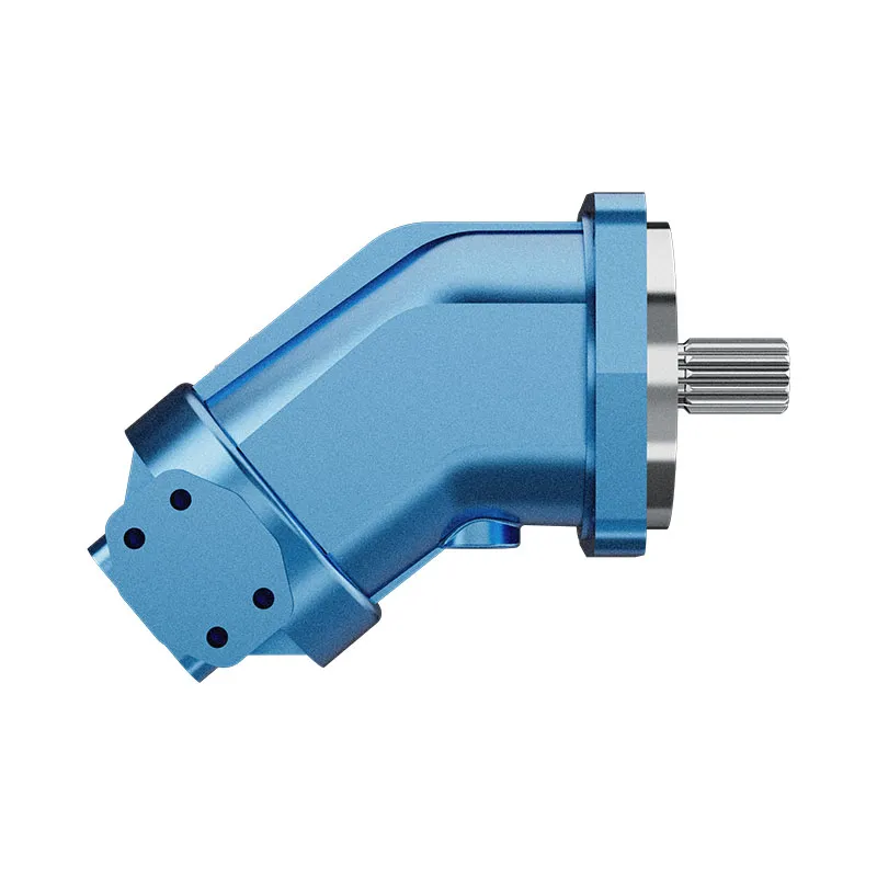
Pressurized oil acts on pistons and creates a turning moment through the motor's internal geometry. In a bent-axis design, the cylinder-block axis is inclined relative to the shaft. In a swash-plate design, the piston group interacts with an inclined plate. The details of force transmission, bearings, port timing, and displacement control depend on the specific construction.
These mechanisms describe internal arrangements, not interchangeable commercial specifications. A fixed bent-axis unit cannot be compared directly with a variable swash-plate unit without considering the benefits and costs of displacement control. Likewise, two variable motors may use different control signals, displacement ranges, default positions, and pressure limits.
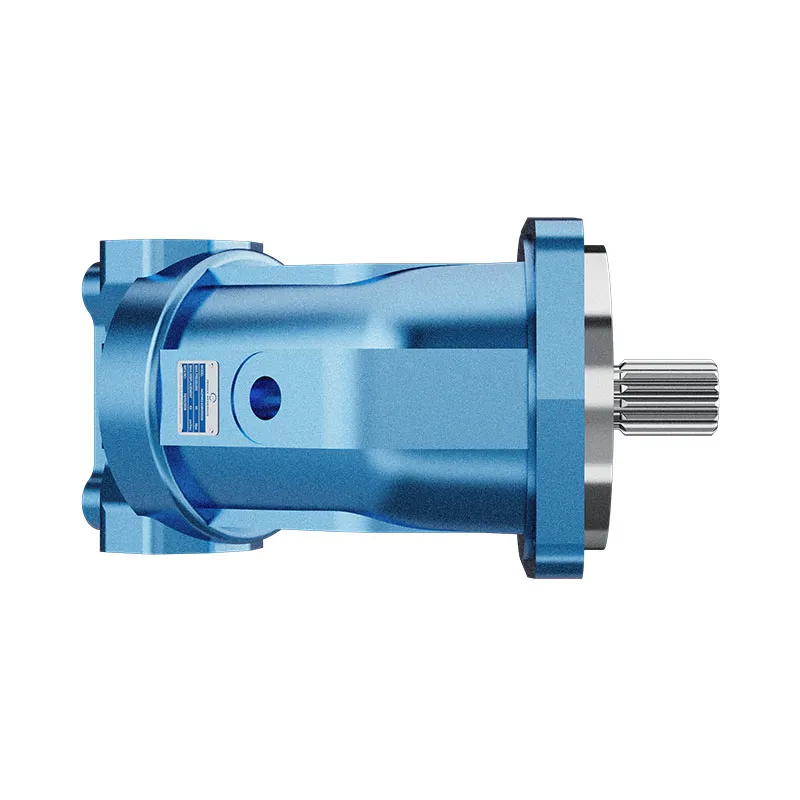
Use a sectional drawing and an identified model specification to confirm the design. A housing photograph can help explain mounting and port access but cannot prove the internal configuration. Similar family names, displacement labels, or bolt patterns are insufficient evidence that two motors can replace one another.
Establish a common operating point
Start with output torque and shaft speed. For an initial calculation, theoretical torque in N m equals pressure difference in bar multiplied by displacement in cubic centimetres per revolution, divided by 20 pi. Estimated output torque then includes mechanical efficiency. The pressure difference is measured between the work ports; pump pressure alone is insufficient when return pressure is significant.
Theoretical speed in rpm equals 1000 times flow in litres per minute divided by displacement. Estimate actual speed by including volumetric efficiency at the operating point. Efficiency varies with speed, pressure, temperature, and condition, so a single advertising figure should not be inserted into every part of the duty cycle.
For illustration, a 50 cubic centimetre motor at 200 bar has theoretical torque of approximately 159 N m. At 40 litres per minute, theoretical speed is 800 rpm. If mechanical and volumetric efficiencies are each assumed to be 0.90, estimated shaft torque is 143 N m and speed is 720 rpm. Those assumed values explain the calculation and are not Prance specifications.
Check whether the motor can operate continuously at that combination. Separate continuous, intermittent, and peak limits. A maximum pressure printed beside a maximum speed does not necessarily mean both can occur together. Ask for the relevant operating envelope and any restrictions on temperature, inlet conditions, and displacement setting.
Fixed versus variable displacement
A fixed motor has one nominal displacement. Speed changes mainly with available flow, while output torque changes with pressure difference. This can simplify commands and fault diagnosis, but a very broad speed requirement may create substantial flow demand or unfavorable operation at the lowest speed.
A variable motor changes displacement to trade torque capability against speed for a given hydraulic input. Smaller displacement can increase speed at the same flow, but theoretical torque also falls at the same pressure difference. Changing displacement does not create additional shaft power; losses and operating limits still apply.
Describe how the machine should respond to loss of command, pilot pressure, or electrical power. The default displacement position can affect acceleration and braking. Verify the actual control option rather than assuming that all motors within a product family fail to the same position. This distinction is especially important in a retrofit using an existing controller.
Compare complete configurations
The table below provides practical questions rather than a universal ranking. The underlying piston-motor principles are described in NPTEL's oil-hydraulics course. Numerical acceptance limits must come from the selected motor documentation.
| Elemento de selección | Bent-axis motor review | Swash-plate motor review |
|---|---|---|
| Required output | Verify running and starting torque at the actual duty | Verify the same torque and speed points rather than peak claims |
| Available envelope | Check angled housing, mounting clearance, and port access | Check housing length, control clearance, and connection access |
| Control de desplazamiento | Confirm whether the ordered unit is fixed or variable | Confirm the ordered range and control mechanism |
| Low-speed motion | Request demonstrated smooth operation under load | Request demonstrated smooth operation under the same load |
| Bearing loading | Obtain permitted radial, axial, and moment loads | Obtain the corresponding limits for the exact shaft option |
| Braking duty | Verify backdriving, replenishment, and pressure transients | Verify the same conditions during stopping and displacement changes |
Starting torque and smooth creeping
Machines that begin with a loaded conveyor, drum, or rotary table need useful torque before motion becomes established. Compare documented starting behavior at the expected pressure difference and fluid condition. Continuous running torque does not by itself establish breakaway torque or reliable restart after a long dwell.
At very low speed, internal leakage, friction, load variation, and valve resolution can create uneven motion. Test the motor with the proposed valve and actual load. A smooth unloaded demonstration can hide stick-slip behavior that appears when the drive must move a loaded machine slowly.
Decide whether a gearbox provides a better operating region. A faster motor with reduction may meet a slow-output requirement, although gearbox losses, backlash, and maintenance must be included. Evaluate the whole drive rather than forcing a particular piston geometry to meet every operating speed directly.
Efficiency and cooling across the duty cycle
Request performance at several representative points: cold start, normal running, hot oil, low-speed load movement, and short peak events. Distinguish volumetric efficiency, which relates input flow to speed, from mechanical efficiency, which relates theoretical torque to useful torque. Overall efficiency combines these effects.
Calculate heat from the hydraulic input and mechanical output. Hydraulic power in kW is approximately pressure difference in bar multiplied by flow in litres per minute divided by 600. Shaft power is approximately torque in N m multiplied by speed in rpm divided by 9550. Their difference estimates motor losses at a steady operating point.
Include valve throttling, gearbox loss, and other circuit heat in the cooling assessment. A motor's best efficiency point is not representative of a drive that spends most of its shift creeping or frequently accelerating. Confirm that reservoir, cooler, filtration, and oil-temperature limits cover the complete cycle.
Case drainage, oil fill, and installation
Check the exact motor's case-drain requirements and permitted case pressure. A drain is not simply another low-pressure return connection. Restrictive fittings, shared drain lines, cooler pressure loss, and simultaneous machine functions can increase pressure at the housing and stress the shaft seal.
Installation orientation may affect oil filling and drain-port selection. Follow the selected manual before the first start. Do not assume that advice for a similar housing covers all bearing arrangements or control options. Record the approved fill procedure and ensure that the drain route remains effective in each machine position.
Compare the flange, pilot diameter, shaft length, spline or key geometry, work-port threads, drain connections, and rotation convention. A mechanically close replacement can still introduce poor coupling engagement or an unsuitable pipe route. Include service access and safe removal clearance in the installation drawing.
Braking and overrunning loads
When a load drives the motor, its operating state differs from positive motoring. The low-pressure side needs adequate replenishment, and the circuit needs a controlled energy path. Examine work-port pressure peaks, brake release, counterbalance behavior, and the response during reversal or command loss.
Neither piston arrangement should be treated as a guaranteed parking brake. Internal leakage allows movement under some load conditions. For a suspended or hazardous load, specify the appropriate mechanical holding and hydraulic control functions through the machine's engineering process. Confirm behavior independently of normal running performance.
During maintenance, isolate electrical and hydraulic energy, release trapped pressure according to the approved procedure, and support moving loads. NIOSH's hazardous-energy guidance explains why switching off the command alone is insufficient. A motor selection discussion cannot replace a machine-specific isolation plan.
What to include in a quotation request
Provide continuous and peak torque, the speed range, direction, duty cycle, available flow, work-port pressure difference, return pressure, temperature range, fluid requirements, external shaft loads, and circuit type. Attach a mounting drawing and specify control signals, braking behavior, and feedback requirements.
Ask suppliers to identify the complete ordered configuration, including shaft, ports, displacement control, default position, seals, and accessories. Obtain curves and installation instructions before approval. A quotation for an unspecified motor family is difficult to verify and can conceal important differences between otherwise comparable proposals.
For a retrofit, record the original motor's settings and measure the machine's operating conditions. Compare required output at the final shaft, including the gearbox ratio, rather than copying displacement from the old nameplate. Investigate the original failure so that a new motor is not installed into the same unresolved drain, contamination, or alignment problem.
Preguntas frecuentes
Is a bent-axis motor an axial piston motor?
Yes. Bent-axis and swash-plate arrangements are both axial piston mechanisms. The angle in a bent-axis design distinguishes its internal geometry; it does not make the motor a radial piston unit.
Is one design always more efficient?
No universal ranking applies to every duty. Compare verified performance at the same pressure difference, speed, displacement, temperature, and fluid condition. Include the gearbox and control losses when assessing the complete drive.
Can I replace one mechanism with the other?
A replacement may be possible after checking output duty, control behavior, mechanical interfaces, drainage, bearings, and braking. Similar displacement and mounting holes alone do not establish a safe or useful replacement.
Does variable displacement increase power?
It changes the torque-speed trade-off. Reducing displacement can increase speed at the same flow but reduces theoretical torque at the same pressure difference. Available input power, efficiency, and component limits still govern output.
Which mechanism should I choose for slow movement?
Require suitable starting torque and stable loaded operation at the lowest speed. Compare the actual motor-and-control arrangement, including any gearbox, instead of choosing solely from the internal piston geometry.
Related products and engineering guides
For a duty-based enquiry, review Motor de pistones axiales de eje encorvado de desplazamiento fijo AA2FM. Confirm the complete ordered configuration, drawings, operating conditions and integration responsibilities with the supplier. Related resources: Gamma de motores de pistón, Calculo de la eficiencia del motor, case-drain flow measurement, starting versus running torque, Radial Piston vs Axial Piston Motor: Application Differences, Hydraulic Motor for Winches: Torque, Braking, and Drum Speed.
University lesson: hydraulic motors
This NPTEL-NOC IITM university lecture explains the motor torque and flow principles used for the duty calculations above.

Technical references
- NPTEL: Fundamentos de la hidráulica y la neumática industriales
- NIOSH: prevención de lesiones por energía peligrosa
- NPTEL: motor and hydrostatic transmission learning material
These sources provide technical, educational and safety context. Example calculations are illustrative, and neither their inputs nor another manufacturer’s component data establish a Prance product rating or brand affiliation.