Wenzhou Prance Hydraulic Equipment Co., Ltd.

Proportional Valve Ramp Time: Smooth Motion and Response Tradeoffs
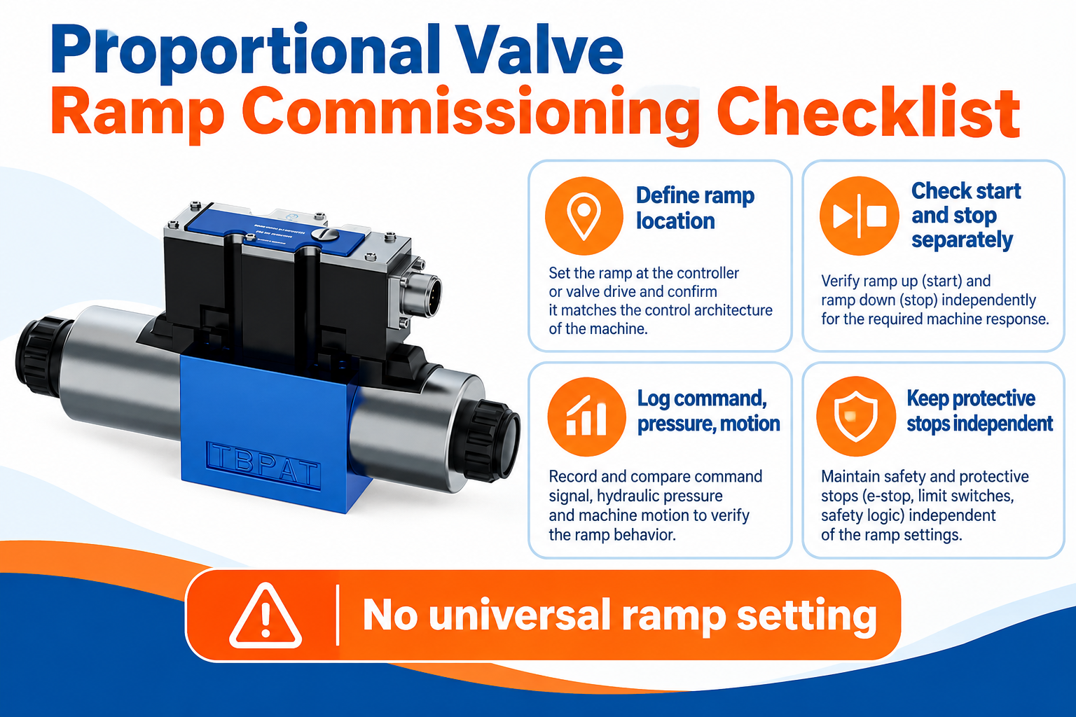
Proportional valve ramp time describes how gradually a command changes between defined levels. It is used to shape starting, stopping, or pressure changes, but it is not the same as valve response time or machine acceleration time. A longer ramp reduces command slope; actual motion still depends on valve characteristics, pressure conditions, actuator geometry, load, friction, and control architecture. Specify the ramp’s location, endpoints, direction, and timing convention before choosing a setting. Test startup and stopping separately, and keep the machine’s protective stopping functions independent of an ordinary process ramp.
Identify what is being ramped
A ramp may be implemented in a PLC, a motion controller, a valve amplifier, or integrated valve electronics. The changing quantity might be a normalized command, current demand, pressure reference, or velocity reference. These are different layers in the control chain. Calling all of them valve ramp time can hide why a machine responds slowly or why two apparently identical settings behave differently.
Start by drawing the signal path from the operator’s request to the hydraulic element. Identify every block that can limit the rate of change. If a PLC already ramps its analog output and the amplifier also applies a ramp, the final command may differ from either individual setting. Do not compensate blindly by increasing gain or removing a limit without understanding the combined behavior.
The NPTEL proportional-valve educational material linked below discusses ramp-up and ramp-down adjustments in proportional control cards. Its role here is to establish the control concept. It does not establish the adjustment range, connector wiring, software parameters, or response of a particular Prance valve. Obtain those details for the complete valve and electronics code being supplied.
Separate ramp time, valve response, and actuator motion
Command ramp time is a deliberate input-shaping choice. Valve response describes how the valve reacts to a defined input under stated conditions. Actuator response describes the resulting movement or force. A fast valve can receive a slow ramp, and a rapid command can produce slow machine motion if the hydraulic supply or load prevents the requested change.
For a directional proportional valve, the command influences spool position or metering behavior according to its design. Flow through the opening also depends on pressure differential. Consequently, a linear electrical ramp does not guarantee a linear flow ramp, and a linear flow ramp does not necessarily give constant acceleration when the load, leakage, or operating geometry changes.
This distinction matters when comparing test results. Define where timing begins, which signal is measured, and what event marks the end. A command changing from 10% to 90%, a spool reaching a specified position, and an actuator reaching 90% of final speed are separate measurements. A single number without these definitions cannot support a meaningful response comparison.
Calculate command slope with explicit endpoints
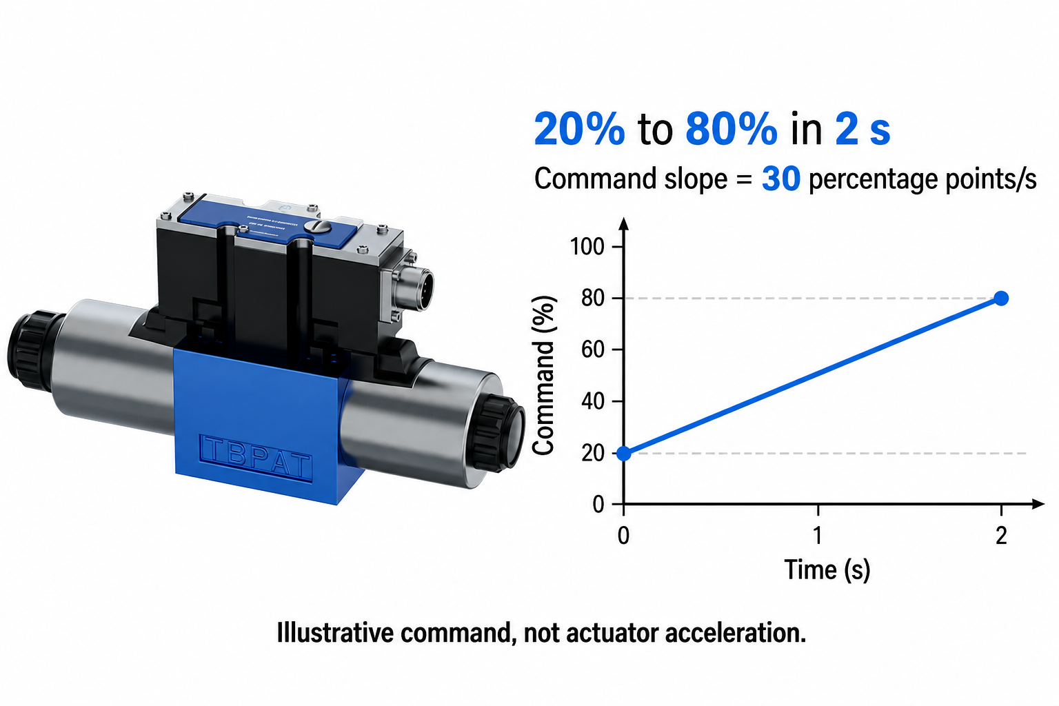
For a simple linear command, slope equals change in command divided by elapsed time. If a normalized command rises from 20% to 80% over two seconds, the slope is 30 percentage points per second: (80 − 20) / 2 = 30. This is a hypothetical command example, not a recommended machine setting or a valve rating.
The distinction between percent and percentage points avoids ambiguity. The command has moved through 60 percentage points of its full scale. That does not mean shaft speed increased by 60%, or that flow has increased by a known amount. The relationship between the command and the controlled physical quantity must be established separately.
Check whether a controller defines ramp time for a full-scale transition or the particular transition requested. Under a full-scale rate convention of two seconds from 0% to 100%, the slope is 50 percentage points per second, so a 20%-to-80% change takes 1.2 seconds. Under an endpoint-duration convention, the same partial transition may take the full two seconds. Both descriptions can appear plausible in a specification; only the actual parameter definition resolves the difference.
For a signed command that crosses zero, determine whether the electronics apply separate deceleration and acceleration segments, a continuous signed slope, or another rule. Do not infer the reversal behavior from an unsigned 0%-to-100% example. Include any neutral dwell, interlocks, and directional state changes in the functional description.
Choose a setting from the process requirement
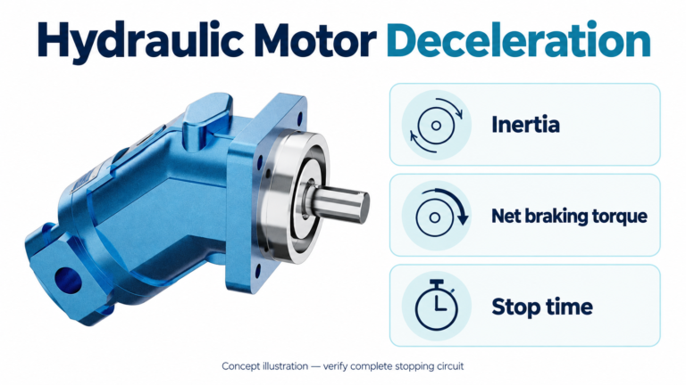
Begin with the motion the machine needs rather than a familiar ramp number. Define acceptable starting shock, travel time, stopping distance, pressure excursion, and cycle consistency. For a rotating load, include inertia and any possibility of the load driving the motor during deceleration. For a cylinder, include load direction and whether gravity or external force can drive motion.
A longer starting ramp may reduce abruptness but can leave a mechanism near breakaway conditions for longer. Friction, valve overlap, load torque, and minimum controllable flow can cause a delayed start followed by a sudden change. If increasing ramp time merely extends the delay, examine the operating point and control chain rather than assuming the ramp is still too short.
A longer stopping ramp may allow smoother process motion but increase stopping distance. An overrunning load also needs an appropriate hydraulic braking and makeup arrangement. A decreasing command alone does not prove controlled deceleration. Check the circuit, available pressure conditions, and load energy against the engineered stopping requirement.
Use a decision table during commissioning
The following table provides qualitative diagnostic directions. It does not prescribe universal parameter values. Make changes only within the supplier-approved commissioning procedure and the machine’s controlled operating envelope.
| Observed behavior | Question to investigate | Useful evidence to record |
|---|---|---|
| Long delay before motion, then a jump | Is the command crossing valve overlap or static friction before movement begins? | Command, motion onset, pressure differential, load, and oil temperature |
| Smooth start but excessive stopping travel | Are startup and deceleration settings being treated as one parameter? | Stop request, actual command, speed or position, and stopping distance |
| Slow response despite a short ramp | Is another controller or amplifier applying additional shaping? | Signals before and after each rate-limiting block |
| Speed changes with the same ramp under different loads | Does changing pressure differential alter metered flow? | Command, load condition, actuator speed, and relevant pressures |
| Oscillation after the ramp ends | Are feedback tuning, hydraulic compliance, or mechanical effects involved? | Synchronized command, feedback, pressure, and repeated operating conditions |
| Unexpected motion during reversal | How are signed commands, neutral crossing, and directional interlocks handled? | Direction state, signed command, measured motion, and transition timing |
Compare one controlled change at a time. If ramp duration, controller gain, maximum command, and pressure settings all change together, the next test may look better without revealing why. Preserve the previous settings and the reason for the change so the final configuration can be reproduced and reviewed.
Understand the interaction with feedback control
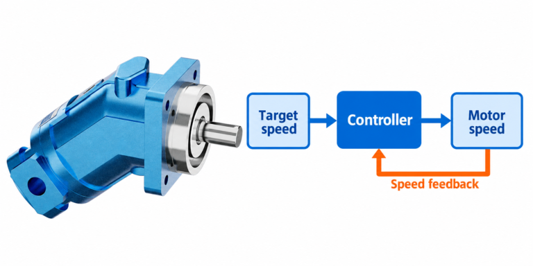
In an open-loop arrangement, command shaping changes the input without measuring whether the machine follows the desired motion. It may improve consistency for a known load, but it does not automatically correct load disturbances. In a closed-loop system, the ramp may shape the setpoint while a controller adjusts the actuator command to follow it. Those two signals should be distinguished in the test record.
An additional ramp applied after a feedback controller can limit how quickly its correction reaches the valve. That can matter for tracking, disturbance response, and saturation handling. A ramp before the controller may instead describe the desired process trajectory. Neither arrangement is universally wrong; the control design must account for the chosen location and all associated limits.
When the valve cannot provide more flow or the drive reaches a pressure limit, the machine may fail to follow the requested ramp. Repeatedly shortening the input ramp will not restore unavailable capacity. Ask whether the controller handles saturation and whether the desired trajectory remains feasible across the specified load and temperature range.
Verify the valve and electronics as a complete combination
Prance’s 4WRAE page provides a real proportional-valve exterior and describes direction and flow control with associated electronics. The product reference does not justify assuming a particular adjustable ramp feature, current setting, connector pin assignment, or software interface. Confirm the complete model code and the documentation that applies to that combination.
Specify supply requirements separately from command signals. A power supply voltage does not tell an integrator the command scaling or permissible input connection. Likewise, coil current, PWM switching behavior, dither, and a slow command ramp describe different functions. Avoid changing a coil-drive parameter to solve an incorrectly defined process ramp.
Do not treat the spring-centered description of a valve as proof of a machine safety function. The final stopped condition depends on spool configuration, circuit arrangement, leakage, load, external energy, and the applicable protective design. Ordinary process deceleration must not be the only assumed protection against dangerous movement. The hazardous-energy reference below explains why stored and unexpected energy require deliberate control.
Plan a useful acceptance test
Define the test load, fluid temperature range, supply conditions, permitted operating envelope, and measurement points before testing. Include the normal cycle and credible demanding conditions. A no-load trace is useful for identifying the command path, but it cannot establish loaded stopping behavior or the response of a machine under an overrunning condition.
Record the requested trajectory, actual valve command, motion feedback, and relevant pressure signals on a common time basis. State the sampling method and any filtering that could hide peaks or delay an apparent response. Note whether the displayed command comes from the PLC output, amplifier input, internal demand, or another signal; a screen label alone may not identify the actual measurement point.
For each trial, compare delay to motion, acceleration behavior, final speed or position, pressure excursions, and stopping travel with the predefined acceptance criteria. Repeat at the same conditions to assess consistency. If the result is unacceptable, identify whether the issue belongs to command definition, valve behavior, hydraulic capacity, load dynamics, or feedback design before choosing the next adjustment.
Put an unambiguous ramp requirement in the RFQ
Write the required command transition, units, endpoints, direction, duration convention, and location in the signal chain. State whether rising and falling commands need separate settings and how reversals should behave. Include the required motion result, load conditions, available supply, valve code, and control interface so the supplier can evaluate feasibility rather than simply quote an adjustable parameter.
Ask who owns parameter setup, software documentation, commissioning, and final acceptance. Request the approved setting record and a description of behavior after power loss, signal loss, restart, and protective stop. A useful specification describes what the machine must do and how that result will be checked. It does not turn an illustrative two-second command into a universal recommendation.
Preguntas frecuentes
Is proportional valve ramp time the same as response time?
No. Ramp time describes deliberate shaping of a defined command. Valve response describes the valve’s reaction to an input under specified conditions. Machine motion adds load and hydraulic dynamics, so its timing must be measured separately.
Does a linear command ramp produce constant acceleration?
Not necessarily. Valve flow characteristics, pressure differential, friction, leakage, and load affect the motion. Define the desired trajectory and verify actual actuator response rather than assuming it from the electrical command shape.
Should ramp-up and ramp-down use the same duration?
Only if the process and validated design justify it. Starting and stopping have different load and energy conditions, and stopping distance may constrain deceleration. Specify and test each transition separately.
What does a two-second ramp setting mean?
It depends on the controller definition. It may mean two seconds for a full-scale change or two seconds between the requested endpoints. Check the manual and record the exact command transition before calculating slope or comparing results.
Can I rely on the normal ramp for an emergency stop?
Do not assume that an ordinary process ramp provides a protective stopping function. The machine’s protective design, energy control, load behavior, and required stopped state must be assessed and verified independently.
Recursos de producto y ingeniería relacionados
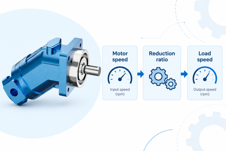
The Proportional Valve 4WRAE catalog exterior is used as the real product reference in these explanatory images. It does not establish the approved service method, optional construction, or operating limits for an individual order. Confirm the complete code and its documentation. Related resources: Válvula proporcional 4WRAE, Gamma de válvulas hidráulicas, Tiempo de respuesta de la válvula hidráulica: medición y factores que la influyen, Ajuste nulo de la válvula hidráulica: controles servo y proporcionales.
Sources and limits of this guide
University references support the stated physical and control principles; the NIOSH source supports hazardous-energy precautions. Calculations are explicitly hypothetical. No linked source supplies ratings, wiring, approval, or a validated installation for the illustrated Prance product.
- NPTEL Fluid Power Control: proportional valves and amplifier ramp-up/ramp-down
- NPTEL: Industrial Oil Hydraulics and Pneumatics, motor and fluid-power principles
- NIOSH: prevención de lesiones por energía peligrosa
University lesson: operating principles
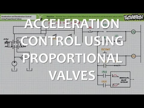
Jim Pytel presents Acceleration Control Using Proportional Valves (Full Lecture). The lesson supports the deliberate command shaping and acceleration control using proportional valves; the lecture is educational and not a Prance setting recommendation used in this discussion; it is not a model-specific performance or installation approval.