Wenzhou Prance Hydraulic Equipment Co., Ltd.

Hydraulic Pump Suction Hose Collapse: Vacuum Rating, Routing, and Diagnosis
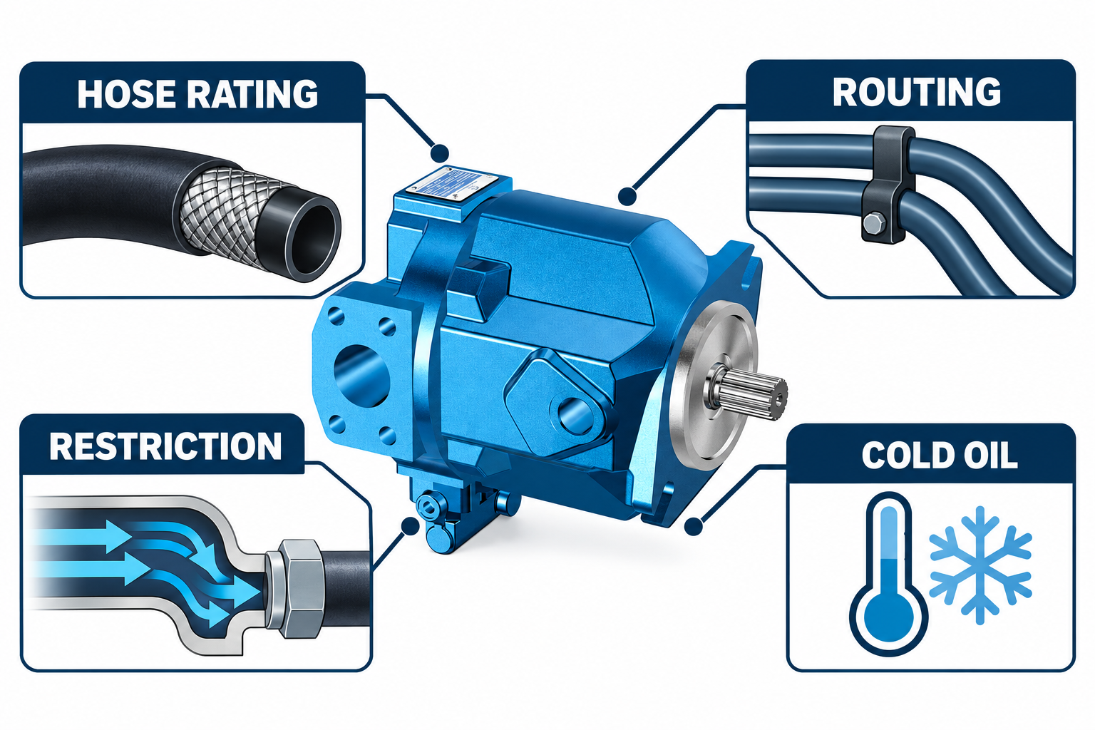
A hydraulic pump suction hose can collapse when the pressure inside it becomes sufficiently lower than the pressure outside and the hose assembly cannot resist that external loading in its installed condition. The problem may involve an unsuitable vacuum rating, damaged reinforcement, a tight bend, an upstream restriction, or demanding cold-oil conditions. Replacing the hose without investigating the pressure conditions can leave the cause unresolved. A positive working-pressure rating alone does not establish resistance to collapse under suction.
This guide focuses on hose-wall behavior. It complements inlet-vacuum and line-sizing reviews, but it does not provide a universal vacuum limit, hose construction, or replacement specification for every pump installation.
Understand the pressure difference across the hose wall
A suction connection supplies fluid to the pump. Depending on reservoir pressure, elevation, fluid condition, and flow resistance, pressure within part of the line may be below the surrounding atmospheric pressure. The hose wall then has to resist a loading direction different from the internal positive pressure emphasized in many hose descriptions.
Do not describe the pump as simply creating a fixed amount of suction that every hose must withstand. Actual pressure conditions change with the installation and operating state. Determine the permitted inlet conditions for the exact pump and the vacuum capability of the complete hose assembly. The weakest relevant element may be the hose, its routing, a fitting, or another component in the inlet path rather than the nominal pump port size.
Distinguish vacuum suitability from a pressure label
A hose intended to contain high positive internal pressure is not automatically suitable for the required suction service. Its construction and the manufacturer’s stated capability must match the loading, fluid, temperature, and installation. Verify the complete assembly specification rather than relying on a generic term such as hydraulic hose.
Ask for the applicable vacuum rating and its conditions, fluid compatibility, temperature range, minimum bend radius, coupling arrangement, and installation requirements. Do not assume that reinforcement visible in a cutaway photograph proves the capability of another hose. The conceptual cross-sections in this article explain round versus flattened shape; they do not specify reinforcement layers or certify that the pictured pump requires a particular hose construction.
Recognize that a restriction can be upstream of the visible damage
A partly closed isolation valve, an unsuitable or restricted inlet component, a contaminated strainer where fitted, or another obstruction can increase the pressure loss between the reservoir and pump. The hose may be the visible part that deforms while the initiating restriction is elsewhere. A new, stronger hose may conceal that symptom without restoring acceptable inlet conditions.
Map the complete inlet path before replacing individual parts. Identify the reservoir outlet, any service valves, fittings, flexible sections, and inlet accessories. Confirm actual positions and specifications using the approved drawing. Do not remove a filter, bypass a protective arrangement, or open an unidentified connection as an improvised diagnostic shortcut. Changes need to preserve the machine’s intended fluid and contamination controls.
Check routing, support, and movement
A tight bend can deform a hose even before the pump runs. Twist, external compression, poor support, rubbing, or movement during machine operation can also alter its shape or damage its construction. Inspect the actual routing with guards and neighboring equipment considered, not only the relaxed hose after removal.
Compare the installation with the hose supplier’s limits and assembly instructions. A hose that fits between two connections may still be too short for movement or too tightly bent near a coupling. Avoid forcing the pump connection or hose end into alignment. If the machine changes attitude or components move relative to each other, review the complete operating range rather than accepting one stationary workshop position as the whole installation.
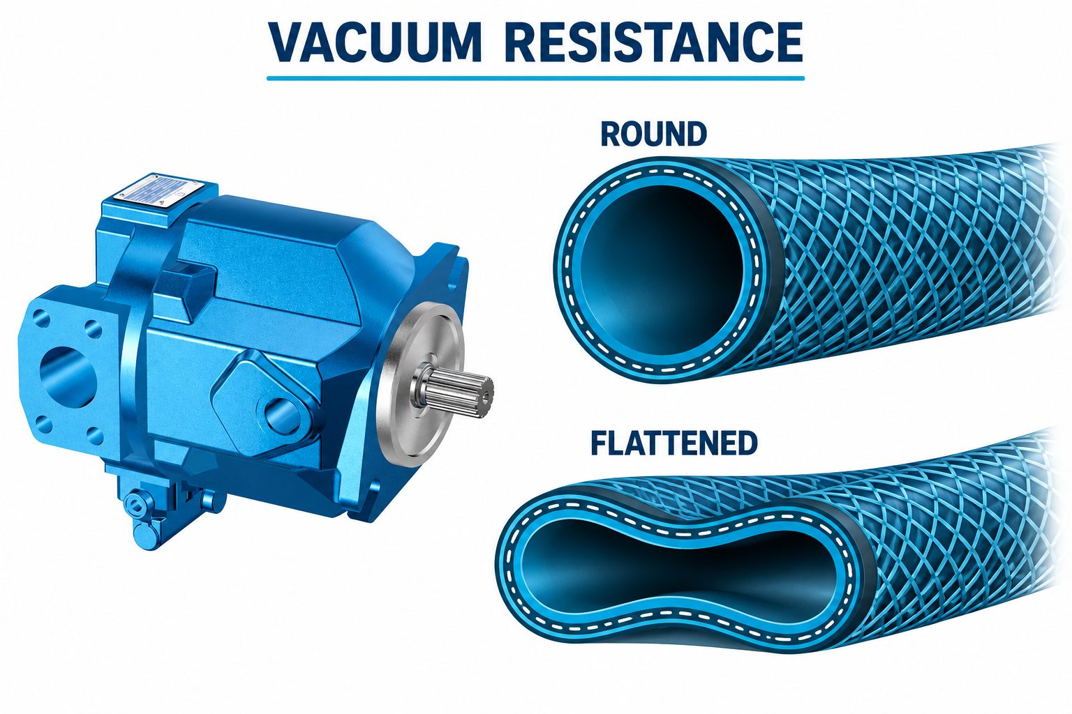
Account for cold oil and startup conditions
Fluid viscosity affects the pressure loss through an inlet path. Conditions during a cold start can therefore differ from a warm operating check. A hose that appears stable after the machine reaches temperature may still have been exposed to an unsuitable condition earlier in the cycle.
Record the actual fluid, temperature, shaft speed, and operating demand when the symptom occurs. Compare cold and warm observations under the approved test procedure. Do not increase speed repeatedly to make a hose flatten for demonstration, and do not assume that warming the machine makes the original installation acceptable. The recovery plan may need to address the inlet route, specified fluid, starting procedure, or other design conditions rather than treating hose replacement as the only action.
Separate visible flattening from hidden internal damage
An outside visual check is valuable but limited. Some hose defects or restrictions may not be obvious from the external shape. A section that looks round when the machine is stopped can behave differently under operating pressure conditions. Other problems, including internal deterioration, can reduce effective flow area without producing an easily recognized external collapse.
Preserve the removed assembly for competent inspection when the cause is uncertain. Do not cut a connected hose, probe an opening in an energized system, or run with an unapproved transparent substitute to watch the fluid. Use a controlled assessment and suitable measurement equipment. The purpose is to establish the condition and its cause without creating a new exposure to fluid, moving parts, or stored energy.
Use a diagnostic evidence table
| Observación | Question it raises | Evidence to collect safely |
|---|---|---|
| Hose is flattened before startup | Is routing, bend radius, twist, or external compression unsuitable? | Installed geometry and the hose assembly instructions |
| Shape changes during operation | Are pressure conditions exceeding the assembly’s capability? | Approved inlet-pressure measurement and operating conditions |
| Symptom appears mainly when cold | Are viscosity and startup demand increasing inlet loss? | Fluid identity, temperature, speed, and cold-versus-warm records |
| New hose repeats the symptom | Has the upstream restriction or routing cause remained? | Complete inlet-path review and exact replacement specification |
| Pump symptoms remain without obvious deformation | Is there another inlet defect or internal hose restriction? | Qualified hose inspection and broader inlet-system diagnosis |
| Coupling area is distorted or damaged | Is the assembly or installation applying an unsuitable load? | Coupling identity, bend location, support, and assembly history |
These are investigation prompts, not diagnoses from appearance alone. Exact acceptance limits come from the pump and hose documentation.
Measure the appropriate pressure at the appropriate location
A useful inlet measurement identifies the test point, reference pressure convention, instrument range, and operating conditions. Gauge vacuum, gauge pressure, and absolute pressure should not be mixed. A reading at the reservoir does not necessarily represent the condition at the pump inlet when pressure loss exists between them.
Use an approved test connection and competent personnel. The selected method must not introduce a significant restriction or air leak that changes the problem being measured. Record the fluid temperature and speed alongside the pressure. Compare the result with the exact pump requirements and hose-assembly capability under the applicable conditions; do not interpret a generic vacuum number found for another pump as the correct limit for this installation.
Specify the replacement as a complete assembly
An appropriate replacement request should identify suction service, fluid, temperature, required flow conditions, connection types, routing, movement, and relevant vacuum requirements. Include the pump’s inlet constraints and the applicable machine drawing. Confirm hose construction and couplings together instead of combining a suitable hose with unverified end fittings or assembly methods.
Check that the replacement does not change the inlet path in a harmful way. A different fitting bore, extra elbow, shorter length, or less flexible hose can change loss or routing even if the external connection fits. Retain the approved specification and installation record. Avoid substituting a used hose of unknown history simply because its size and positive pressure label appear more substantial.
Verify the cause has been corrected
After the machine has been isolated and the approved work completed, inspect routing, support, connection integrity, and fluid readiness before startup. Address any contamination or air entry created during service under the correct procedure. Define the observations that require stopping rather than waiting for severe deformation, abnormal noise, or loss of function.
Use a controlled return to operation covering the relevant cold and warm conditions and required duty. Recheck inlet pressure and other observations selected for the investigation. A hose that no longer visibly flattens is encouraging, but it does not by itself prove that the pump’s inlet conditions are acceptable. Close the job with a documented cause, confirmed assembly, corrected installation, and comparable operating evidence.
Preguntas frecuentes
Does a high pressure rating prevent suction collapse?
Not necessarily. Positive internal pressure and external pressure under suction impose different requirements. Confirm vacuum capability and its conditions for the exact hose assembly rather than inferring it from a working-pressure label.
Can a blocked inlet component cause the hose to flatten?
A restriction can contribute to lower pressure downstream and expose an unsuitable or damaged hose to collapse. Investigate the whole path. The visible deformation does not establish which component initiated the problem.
Is the hose acceptable if it returns to a round shape after stopping?
That does not prove suitability. Its behavior under the relevant operating conditions and the possibility of damage still need assessment. Compare measurements and the assembly specification rather than judging only the stopped appearance.
Should I use a larger hose immediately?
A larger bore may affect pressure loss, but it is not a complete diagnosis or specification. Vacuum resistance, routing, fittings, fluid, temperature, and the pump’s requirements must also be considered before choosing a replacement.
What information should accompany a failure report?
Include the complete hose and pump identities, routing photographs, fluid and temperature, shaft speed, when deformation occurs, safe pressure measurements, upstream component condition, and previous replacement history. Keep measured facts separate from suspected causes.
Recursos de producto y ingeniería relacionados
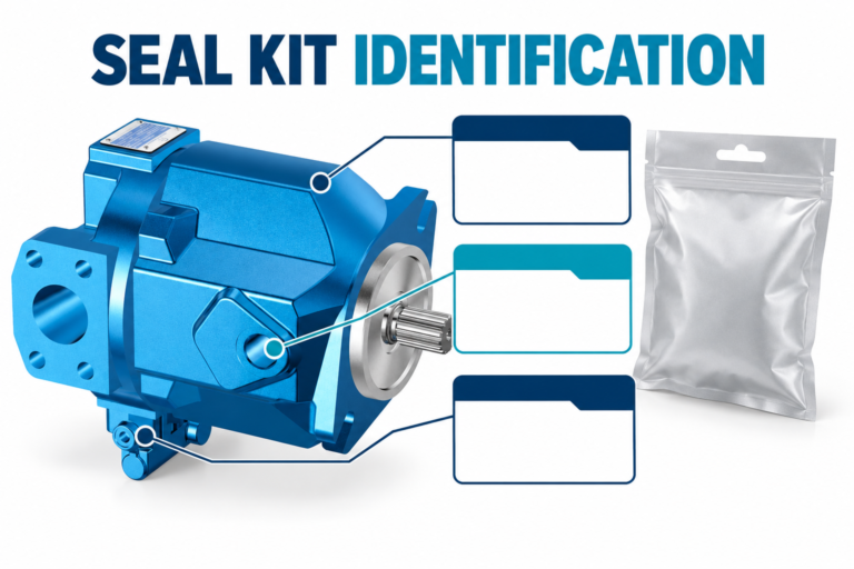
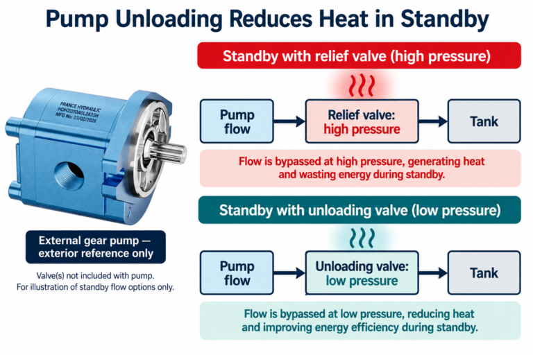
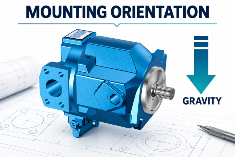
The Variable Displacement Pump OEM A10VO 31 Series catalog exterior is used as the real product reference in these explanatory images. It does not establish the approved service method, optional construction, or operating limits for an individual order. Confirm the complete code and its documentation. Related resources: Bomba de desplazamiento variable OEM serie A10VO 31, gama de bombas hidráulicas, Vacío en la entrada de la bomba hidráulica: Límites seguros y pruebas con manómetro, Dimensionamiento de la línea de succión de la bomba hidráulica: velocidad, vacío y diámetro de la manguera, Aireación vs cavitación en bombas hidráulicas: Síntomas y métodos de prueba.
Sources and limits of this guide
The university resource supports the component operating principles. NIOSH supplies hazardous-energy prevention context; exact machine isolation and component service requirements still need their approved procedures. ISO references identify the stated standard scope. This guide does not reproduce paid clauses or turn their abstract into model-specific limits.
- NPTEL: Fundamentos de la hidráulica y la neumática industriales
- NIOSH: prevención de lesiones por energía peligrosa
- DIN Media: DIN EN ISO 4413, hydraulic fluid power general rules and safety requirements (standard overview)
University lesson: operating principles
NPTEL IIT Guwahati presents Lec 31: Flow control and pressure relief valves. The lesson supports the pump operating principles used in the engineering discussion; it is not a model-specific repair, storage, or installation approval.