Wenzhou Prance Hydraulic Equipment Co., Ltd.

Hydraulic Solenoid Manual Overrides: Diagnostic Uses and Limits
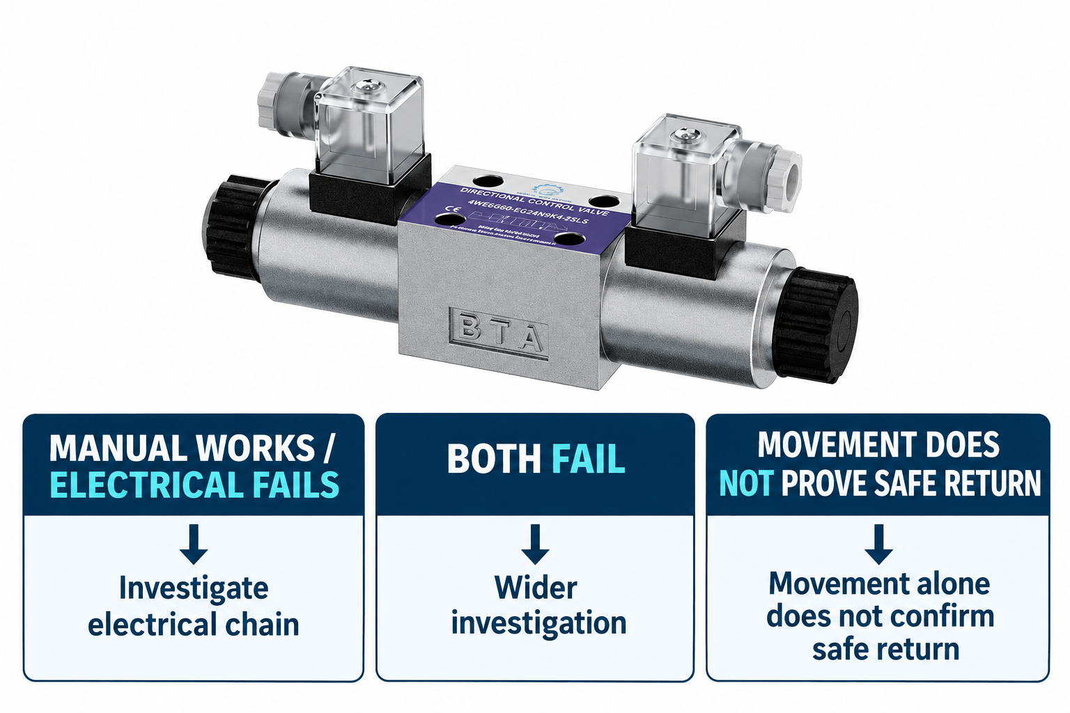
A hydraulic solenoid valve manual override can help compare mechanical actuation with electrical actuation, but it cannot by itself prove that the valve, actuator or safety system is healthy. If an approved manual test produces the expected response while the electrical command does not, investigate the electrical command chain under the specified conditions. If neither produces the response, the cause may extend beyond the coil. Before touching an override, identify the exact valve and follow the machine’s authorized procedure: manual actuation may cause immediate movement even when the electrical control is off.
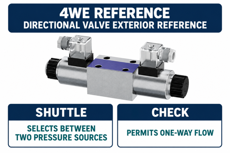
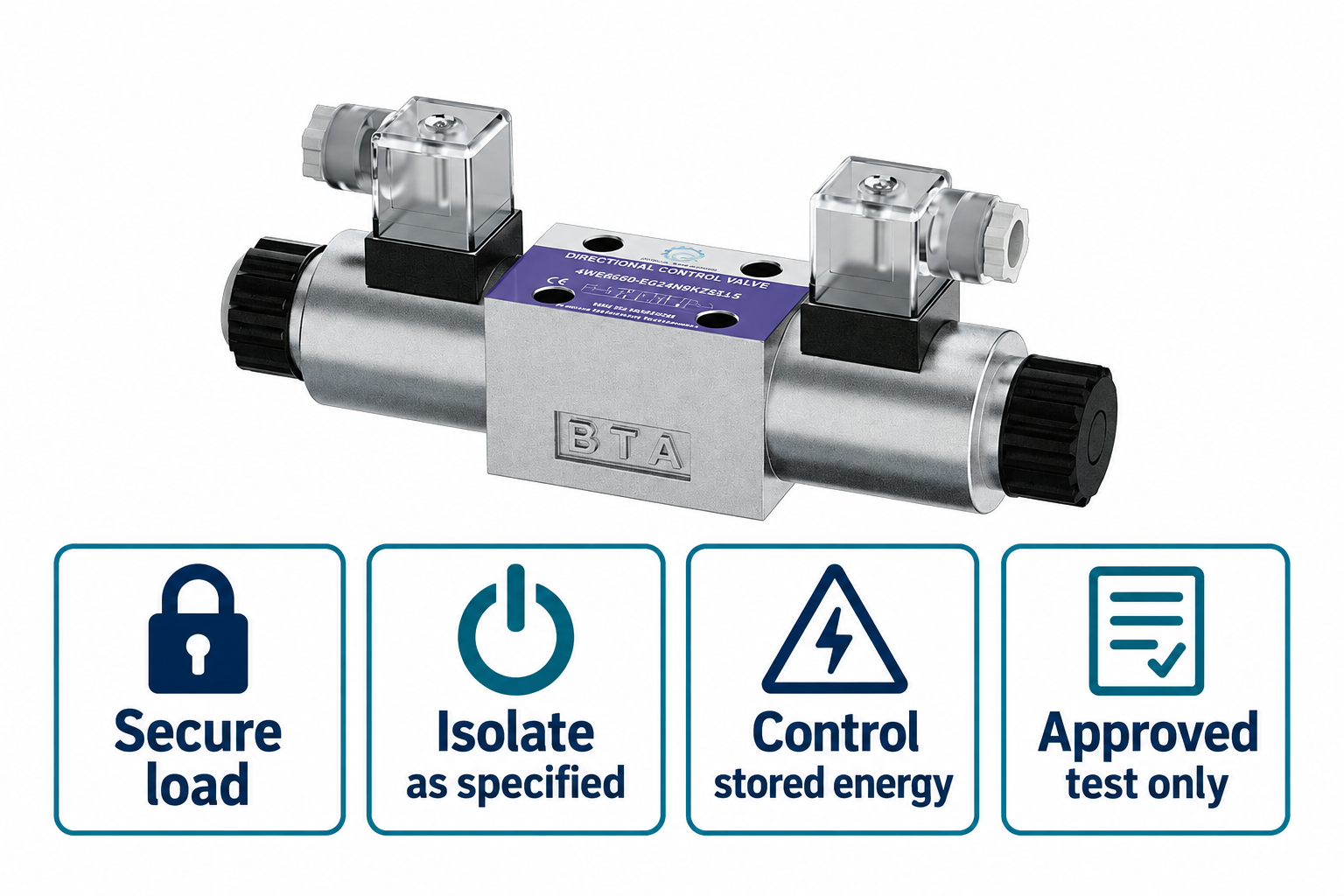
This guide explains diagnostic interpretation rather than giving a live-machine button-pushing procedure. The pictured 4WE catalog exterior is a component reference. It does not establish that every configuration has the same override, operating force, retention behavior or permitted test method.
What the override changes in the actuation chain
A solenoid valve normally receives an electrical command that produces magnetic force and moves an actuation mechanism. A manual override provides a mechanical way to influence the valve’s actuation path. The exact mechanism and the part it acts upon vary with valve construction; some arrangements directly influence a spool mechanism, while other circuits rely on pilot stages and hydraulic conditions.
The useful comparison is therefore limited. Manual operation can bypass some electrical steps, but it does not bypass the need for an available hydraulic supply, a suitable flow path and an actuator that can move under the current load. It also may not reproduce the same stroke, timing or force as normal electrical actuation.
Start with the circuit symbol, the full valve code and the applicable instructions. Identify the normal position, the selected direction and what the connected machine is expected to do. An override operated on the wrong end of a valve can command a different movement from the one the technician intended to compare.
Identify the actual override before testing
Override options can include different push, turn, protected or retained mechanisms, depending on the product. The presence of a cap, recess or end piece does not tell you how it should be used. A design may require a specified tool or a particular release action. Do not apply these descriptions as instructions for an unidentified valve.
Determine whether the mechanism automatically returns when released or can remain engaged. A retained override left active can change what happens when the machine is restarted. That possibility belongs in both the pre-test review and the restoration check, not merely in a maintenance note written afterward.
Check access and component condition with the system in its required safe state. Do not remove a cap or protective feature unless the instructions permit it. Damage, contamination or an uncertain mechanism is a reason to stop and identify the component properly rather than apply more force.
Secure the machine before comparing responses
A manual override can defeat the normal relationship between an operator’s electrical command and hydraulic movement. Turning the control panel off may leave pressure available through an accumulator, gravity load or another supply path. NIOSH hazardous-energy guidance explains why stored energy and unexpected startup must be addressed in a controlled procedure.
The responsible technician must identify the load, exclusion area, energy sources and permitted testing condition. Some diagnostic procedures require controlled energization after isolation and instrument connection; others permit only checks in an isolated state. This article does not authorize either condition for a particular machine. Follow the approved procedure and personnel requirements.
Never use manual override as a way to move a machine with guards open, bypass an interlock or “just get one cycle” after a control fault. A valve responding to mechanical actuation does not establish that the intended safety functions remain available. If access requires entering a movement zone, the method needs an appropriate engineering review before testing.
Manual response with no electrical response
When the procedure permits a comparison and manual actuation gives the expected result, the electrical path deserves attention. The fault could involve the command, controller output, wiring, connector, supply under load, coil compatibility or the solenoid assembly. Manual success does not identify which of those items is defective.
Record the electrical condition at the correct point and time using the specified method. A controller indicator or an unloaded voltage measurement may not represent the coil’s actual condition during a command. Use the correct AC or DC configuration and recognize that connector electronics can affect the circuit. Detailed coil resistance and voltage-drop testing belong in their separate procedures.
Also consider whether the manual action applied a different force or maintained a different duration from normal operation. A marginal mechanical condition may still exist even when a manual response is observed. Avoid replacing only the coil without reviewing the full symptom and checking that the mechanical and hydraulic requirements were the same in both tests.
No expected response from either actuation method
Failure to produce movement can arise from valve actuation, hydraulic supply, pilot conditions, pressure control, load holding, an actuator fault or a blocked path. In a pilot-operated arrangement, moving an override may not create the expected main-stage response if the required pilot supply or drain condition is absent.
Separate a confirmed actuation observation from the machine outcome. A change in a measured valve condition is different from visible actuator movement. Likewise, no actuator movement does not prove that the spool remained stationary. A load-holding component or the load itself may prevent motion even when a directional path changes.
Do not keep increasing manual force until something moves. There is no generic safe force value for every override. If the approved action cannot be completed normally, stop, restore the safe state and investigate using the relevant service method. Striking, extending or wedging the mechanism can damage it and create an uncontrolled command.
An interpretation matrix for recorded observations
The matrix below describes evidence boundaries rather than prescribing energized tests. Use the actual valve instructions and machine procedure to decide which observations can safely be obtained. General fluid-power teaching supports the distinction between command, valve action and circuit response.
| Recorded observation | Investigation direction | Additional evidence needed | Conclusion to avoid |
|---|---|---|---|
| Manual response expected; electrical response absent | Electrical command chain and possible force differences | Correct command, loaded supply condition and configuration | The coil is certainly defective |
| Both responses absent | Valve, supply, pilot and actuator/load paths | Circuit-specific pressure and actuation observations | The spool is certainly stuck |
| Response occurs only while override is held | Compare with the specified return behavior | Override type, spring/retention arrangement and circuit symbol | Every such valve should stay actuated |
| Movement continues after release | Restore safe state and investigate retained command or system behavior | Actual override position, spool state and stored/load energy | Electrical power off guarantees stopping |
| Response differs by direction | Direction-specific valve and circuit review | Complete code, connection map and controlled comparison | Both solenoids have identical operating conditions |
Return behavior is a separate acceptance question
A successful shift is only one part of valve function. The procedure must also establish that the override has been released or reset as specified and that the machine returns to its intended state. Spring-centered, detented and retained arrangements have different behaviors; a technician must not substitute the behavior of a familiar valve for the actual configuration.
The circuit’s neutral condition also matters. A centered directional valve is not automatically a verified load-holding barrier. Actuator movement after release can depend on spool configuration, leakage, load-control components and external forces. Determine the intended stopping and holding functions from the machine design.
Document an unexpected return or continued movement as a distinct symptom. Do not simply record “manual override works.” That shorthand can hide the most important part of the test and lead another technician to assume normal stopping has been demonstrated when only initial movement was observed.
Restore and hand back the machine deliberately
After the authorized test, follow the documented restoration sequence. Confirm the override is in its required position, protective parts are restored, temporary instruments are removed or secured appropriately, and the normal command state is known. These checks must follow the machine’s energy-control and recommissioning procedure.
If an override was found retained or obstructed, record the as-found condition before correction when safe to do so. Include who restored it and how the final state was established. A maintenance handover should make clear whether the machine is released for normal service or remains isolated pending further work.
Do not leave an improvised device holding an override for production use. If the application requires a permanent manual operating mode, select and approve a valve and control arrangement designed for that duty. A troubleshooting aid should not silently become the machine’s operating control.
Information that makes a support inquiry useful
Send the full valve identification, coil marking, connector type and machine schematic. Describe the authorized test conditions, which actuation method was used, which direction was selected, and what was observed during actuation and after release. Include hydraulic measurements only with their test points, units and pressure references.
Explain the original trigger: a recent valve replacement, connector change, control update, cold start or gradually worsening fault. Photographs of the installed configuration can prevent ordering an incompatible override or coil option. Product-family names and voltage alone are often insufficient for selecting a replacement.
Ask for the permitted override method, return or retention behavior and any pilot requirements for the exact code. If the supplier cannot establish those details, retain the safe state and seek a configuration-specific review. A diagnosis should narrow the fault using controlled evidence rather than assume that any visible movement is proof of a healthy valve.
Preguntas frecuentes
Does manual operation prove the electrical coil has failed?
No. It suggests comparing the electrical command chain with the mechanical actuation path, but the fault may lie in wiring, control output, connector or supply conditions. Manual action can also apply different force or duration. Identify the cause before selecting a replacement.
Is it safe to press the override with electrical power off?
Electrical power off alone does not establish a safe state. Hydraulic pressure, accumulators, gravity and other energy sources can still produce movement. Use the machine’s authorized energy-control and diagnostic procedure and the instructions for the exact valve configuration.
Should every override return when released?
No. Return and retention behavior depend on the option fitted and the valve design. Identify whether the mechanism is momentary or retained, and follow the specified reset and restoration method. Never assume the required state from appearance alone.
If neither manual nor electrical actuation moves the actuator, is the spool stuck?
Not necessarily. Supply pressure, pilot conditions, load holding, blocked paths or actuator faults may prevent movement. The diagnostic procedure must distinguish valve actuation from the machine’s resulting motion. Do not increase manual force to compensate for an unidentified cause.
Can manual override be used to keep production running?
A diagnostic override is not general approval to bypass the normal command or safety system. If a manual operating mode is required, the complete valve and machine arrangement needs to be designed and authorized for that duty. Restore the specified safe condition after troubleshooting.
Recursos de producto y ingeniería relacionados
The Directional Valve 4WE catalog exterior is used as the real product reference in these explanatory images. It does not establish the approved service method, optional construction, or operating limits for an individual order. Confirm the complete code and its documentation. Related resources: Válvula direccional 4WE, Gamma de válvulas hidráulicas, ¿Qué síntomas deberían motivar la revisión de una válvula direccional hidráulica?, ¿Cómo se elige entre una válvula hidráulica manual y una solenoide?.
Sources and limits of this guide
The university resource supports the component operating principles. NIOSH supplies hazardous-energy prevention context; exact machine isolation and component service requirements still need their approved procedures. Sources explain general operating principles, not performance ratings or optional features of the pictured catalog component.
- NPTEL: Fundamentos de la hidráulica y la neumática industriales
- NIOSH: prevención de lesiones por energía peligrosa
- DIN Media: DIN EN ISO 4413, hydraulic fluid power safety (standard overview)
University lesson: operating principles
NPTEL-NOC IITM presents 5.1 – Directional Control Valves. The lesson supports the valve operating principles used in the engineering discussion; it is not a model-specific repair, storage, or installation approval.