Wenzhou Prance Hydraulic Equipment Co., Ltd

Soft-Shift Hydraulic Valves: Switching Profiles and Shock Reduction
A soft-shift hydraulic valve reduces the abruptness of a flow-path change through a designed switching profile. It may use hydraulic damping, a selected metering geometry or an approved proportional command ramp. Choose it by the pressure and motion transition the machine needs, then verify both directions of travel and loss of power. A slower electrical command alone does not prove that a conventional on/off valve will produce a controlled flow ramp.
The practical question is where the shock originates. Impact inside the valve, a pressure surge in a line, actuator deceleration and decompression of trapped oil are different events. A suitable soft-shift design addresses the relevant event without creating an unacceptable delay, heat load or loss of control.
Identify the transition that needs improvement
Start by naming the machine operation: starting a cylinder, reversing a motor, stopping travel or releasing a pressurized chamber. Establish when the unwanted event occurs relative to the command, the start of motion and the end of motion. A noise that coincides with armature contact may have a different cause from a line-pressure peak after actuator flow stops.
For a controlled investigation, synchronize the command signal with the relevant pressure and motion observations using an approved instrumentation arrangement. A slow gauge reading can conceal a brief peak. Conversely, an audible change alone does not establish the pressure experienced at a vulnerable port.
Define acceptance in the language of the machine: permitted pressure excursion, stopping distance, cycle time, repeatability and stable motion. Obtain the allowable values from the equipment design. There is no universal soft-shift time that guarantees these outcomes for every hose length, load, pump arrangement or oil condition.
Distinguish three mechanisms often called soft shift
Hydraulic damping controls the motion of a moving valve element by restricting fluid displacement around a designed chamber or pilot stage. The restriction must belong to an approved valve configuration. Its effect depends on the actual mechanism; adding an external restriction in an unrelated return line is not equivalent.
Metering geometry controls how flow area changes as the spool moves. The sequence in which supply, work and return edges open can matter as much as total travel time. A smooth spool movement can still produce an abrupt circuit event if a critical edge suddenly closes a flowing path or connects a compressed volume to tank.
A proportional command ramp changes the input to a suitable proportional valve and controller. It can shape a transition, but the relation between command and actual flow also depends on pressure drop, deadband, load and control response. Confirm the approved driver and valve combination; do not assume that a ramped voltage makes any solenoid valve proportional.
Separate armature cushioning from circuit shock control
Research by Scheidl, Gradl and Plöckinger examines cushioning of solenoid switching-valve moving parts at their end stops. That is an internal impact problem. Their work also describes how an oil film can influence release through stiction. It supports a useful distinction: a valve can land quietly internally while the connected hydraulic circuit still experiences an unfavorable pressure transition.
For a purchasing comparison, ask whether the stated feature cushions the armature, changes main-spool travel, shapes a metering edge or controls an actuator profile. A catalog label such as quiet switching does not answer all four questions. The supplier should identify the feature and the operating conditions behind the claim.
Do not treat an exterior photograph as evidence of a cushioning groove or pilot restriction. Such features may be internal or configuration-specific. A product-family name establishes the category; a complete ordering code and technical document establish the selected option.
Read the flow-path sequence through the whole stroke
Draw the intended connected paths for the start state, transition and final state using the approved symbol and spool information. Note whether flow is blocked, metered to tank, transferred between ports or briefly connected through another route. Examine the reverse transition separately rather than assuming symmetry.
A positive-overlap interval can restrict a moving load before the next path opens. Another arrangement may temporarily connect ports in a way that changes pressure support. Neither label is sufficient by itself to decide suitability. The machine’s load-holding and pressure-control arrangements must remain effective through the complete sequence.
NPTEL’s valve teaching material identifies orifice opening rate, size and opening sequence as important aspects of valve behavior. Apply that framework to the selected spool rather than judging only a published total switching time. Request the actual test conditions if two suppliers quote values that appear directly comparable.
Use a comparison table before choosing a remedy
The table below is a qualitative selection aid. It contains no claimed Prance performance values and does not replace an equipment-specific risk assessment or commissioning procedure.
| Transition problem | Feature to investigate | Acceptance check |
|---|---|---|
| Sharp flow initiation at start | Designed opening profile and appropriate metering edge | Motion begins smoothly without excessive command delay |
| Pressure peak at flow interruption | Closing profile and circuit pressure protection | Peak pressure and stopping distance both remain acceptable |
| Loud internal switching impact | Approved armature or spool cushioning | Noise improvement does not introduce sticking or failed release |
| Harsh reversal with an inertial load | Controlled deceleration, pressure support and reversal sequence | Load remains controlled through the transition in both directions |
| Sudden release of a trapped volume | Dedicated decompression sequence | Stored pressure is released within approved time and motion limits |
A proposed remedy should have a clear link to one row and a measurable acceptance condition. If the symptom is persistent pressure instability rather than a switching event, investigate the control circuit before replacing the valve with a slower version.
Check energy and heat as well as smoothness
A partially open valve can dissipate hydraulic power. For a simple throttling estimate, instantaneous loss is pressure drop multiplied by flow. In practical units, cURL Too many subrequests by single Worker invocation. To configure this limit, refer to https://developers.cloudflare.com/workers/wrangler/configuration/#limits. cURL Too many subrequests by single Worker invocation. To configure this limit, refer to https://developers.cloudflare.com/workers/wrangler/configuration/#limits.
cURL Too many subrequests by single Worker invocation. To configure this limit, refer to https://developers.cloudflare.com/workers/wrangler/configuration/#limits cURL Too many subrequests by single Worker invocation. To configure this limit, refer to https://developers.cloudflare.com/workers/wrangler/configuration/#limits, cURL Too many subrequests by single Worker invocation. To configure this limit, refer to https://developers.cloudflare.com/workers/wrangler/configuration/#limits cURL Too many subrequests by single Worker invocation. To configure this limit, refer to https://developers.cloudflare.com/workers/wrangler/configuration/#limits. cURL Too many subrequests by single Worker invocation. To configure this limit, refer to https://developers.cloudflare.com/workers/wrangler/configuration/#limits.
cURL Too many subrequests by single Worker invocation. To configure this limit, refer to https://developers.cloudflare.com/workers/wrangler/configuration/#limits.
cURL Too many subrequests by single Worker invocation. To configure this limit, refer to https://developers.cloudflare.com/workers/wrangler/configuration/#limits
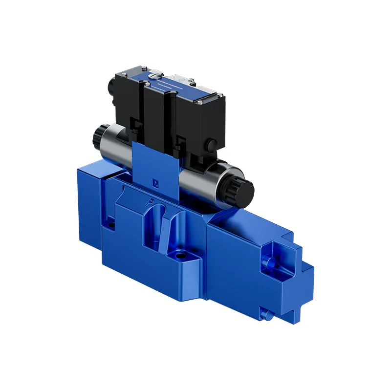
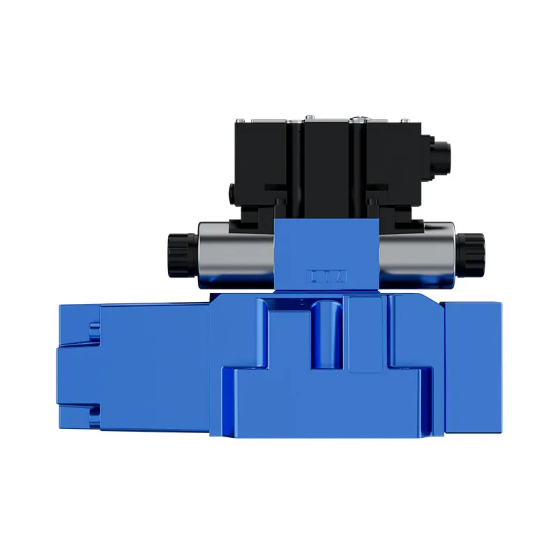
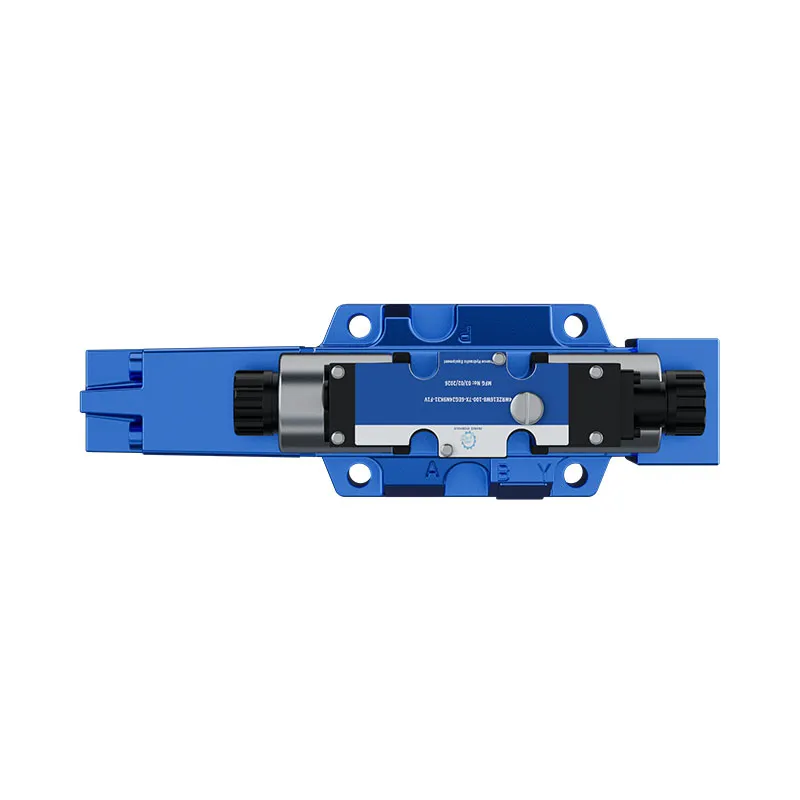
Prance’s 4WRZE listing identifies a related pilot proportional-valve family used in the broader field of directional control. Its original photographs illustrate the component category in this article. They do not establish a particular soft-shift option, programmable profile, closed-loop response or suitability for the machine under review.
Where a proportional approach is proposed, confirm the full valve and driver codes, electrical interface, command range, pilot supply and drain requirements. Ask how the command profile behaves around deadband and when the command returns to zero. A setting copied from a different valve size can give a different flow transition.
For a hydraulically damped on/off solution, request the approved damping option and its documented operating envelope. Do not drill a damping passage, substitute a spring or change a restrictor based on a general article. Those changes can affect release, pressure control and machine sequencing.
Test normal operation and abnormal conditions separately
First establish a repeatable baseline under approved conditions. Change one authorized setting at a time and compare the same load, oil condition and machine state. Record the pressure event and actuator response together. An apparent improvement caused by a lighter load is not evidence that the new profile solved the original problem.
Repeat the acceptance checks across the required cold and warm operating range, both motion directions and representative duty states. Temperature can change viscosity and therefore hydraulic damping. Main-stage response may also vary with available pilot pressure and return conditions. Use the component documentation to define the permitted test envelope.
Include the equipment’s approved power-loss and emergency-stop validation. An operational ramp may depend on a powered controller and may not be available after loss of supply. A soft-shift feature is not a substitute for an independent load-holding function, pressure protection or a validated safety system.
Specify a useful inquiry and a clear stop condition
Provide the supplier with the original valve code, circuit diagram, actuator type, load direction, pump arrangement and the precise transition that causes concern. Include available pressure traces, oil conditions and the permitted change in cycle time. Describe the required result instead of requesting the slowest possible valve.
Ask for a proposal that identifies the selected mechanism, configuration, test conditions and commissioning limits. Where switching time is quoted, establish whether it means command-to-motion delay, spool travel, flow establishment or another defined measurement. Different definitions cannot be compared as if they were one value.
Stop testing if the actuator creeps unexpectedly, stopping distance increases beyond the approved limit, the valve fails to return or pressure becomes unstable. Isolate hazardous energy before inspection or adjustment. Retain the last accepted configuration so that an unsuccessful trial does not become an undocumented production setting.
Foire aux questions
Is soft shift the same as slow response?
No. Soft shift describes an intended transition characteristic. Slow response may result from a fault, inadequate pilot pressure, contamination or an unsuitable command. Diagnose the cause before accepting a delay as an improvement.
Can a command ramp soften an ordinary on/off valve?
Not reliably as a general method. An ordinary solenoid valve may remain stationary until sufficient force develops and then switch abruptly. Use only a valve and driver configuration designed and approved for the required control method.
Will a soft-shift valve eliminate every pressure spike?
No. The result depends on the circuit, load, line dynamics, metering sequence and pressure protection. Verify the particular operating transition, and retain the machine’s required protective functions.
Why check both switch-on and switch-off?
The force, damping path and available command can differ between energizing and release. A gentle start does not prove a controlled stop, especially during loss of electrical power.
Is the pictured 4WRZE a confirmed soft-shift configuration?
No. It is a related original product-family photograph. A specific damping feature or command profile requires confirmation from the complete configuration documents and application review.
Ressources produits et d'ingénierie associées
Valve proportionnelle pilotée pour presse 4WRZE, gamme de produits de vannes hydrauliques, Temps de réponse de la vanne hydraulique : Mesure et facteurs d'influence, Pression de choc hydraulique : causes, calcul et protection. Confirmer le code complet du produit et les exigences d'application lors de la demande d'une revue de configuration.
Références techniques
- JFPS: The Cushioning Groove for Solenoid Switching Valves
- NPTEL: hydraulic flow control and metering
- OpenStax: pressure force and hydraulic area
Further learning: hydraulic valves
mod-12 lec-12 General Control Valve Analysis by nptelhrd provides background on valve functions. The NPTEL lesson explains directional-valve metering and flow paths; it does not certify a particular cartridge, damping option or interchange. It supplements the component fundamentals; it is not a test procedure for the complete circuit discussed above.