Wenzhou Prance Hydraulic Equipment Co., Ltd

Hydraulic Logic Valve Area Ratios: Pilot Pressure and Opening Conditions
A hydraulic logic valve pilot ratio describes the relationship between defined pressure areas, not a universal multiplier for opening pressure. First establish whether the pilot chamber holds the poppet closed or drives it open. Then write the force balance using the actual port pressures, effective areas and spring direction. Dividing system pressure by a catalog ratio without those definitions can predict the opposite switching action.
This guide focuses on two-port slip-in logic elements controlled through a cover and pilot circuit. Screw-in pilot-operated checks and counterbalance valves may use different area definitions. Their published pilot ratios cannot be transferred to a slip-in element simply because both products are called hydraulic logic valves.
Start with the function, not the ratio
A logic element is a controlled flow path. The main cartridge, cover, spring, pilot valve and connecting passages together establish its behavior. The cartridge alone does not tell you whether the assembled function is directional control, unloading, pressure control or a controlled bypass. Obtain the symbol for the complete assembly before assigning an opening condition.
Trace the two main ports and the control chamber separately. Mark the pressure source that feeds the chamber and the route that releases it. A pilot valve can change the chamber pressure without carrying the full main flow. That distinction explains why a small pilot-stage fault may prevent a large main stage from moving even when main-line pressure appears normal.
For a maintenance decision, begin with the machine’s intended state. Should the main path pass flow with the pilot solenoid de-energized, energized or under a particular pressure signal? Record that condition from the approved schematic. Do not infer a safe default from the presence of a spring or the orientation of an exterior photograph.
Define each effective area explicitly
Consider an idealized pilot-to-close element in which pressure at main port A acts on area AA and pressure at main port B acts on annular area AB. Both forces open the poppet. Control pressure pX acts on area AX in the closing direction, together with closing spring force Fs. The naming here belongs to this example; use the manufacturer’s labels for a real component.
For this geometry, AX equals AA plus AB. A catalog might describe the relationship between AA and AB, or between AX and AA. Those are different ratios. If AA is twice AB, AX is one and a half times AA. Calling both quantities a two-to-one pilot ratio would introduce an immediate calculation error.
Projected effective area is also different from an exterior diameter measured across the sleeve. Seal locations, seat diameter and pressure exposure determine the hydraulic force. A photograph, caliper measurement of the outer body or valve nominal size cannot establish these areas. Request the section drawing or the explicit area definition rather than estimating inaccessible geometry.
Write the opening inequality before calculating
For the stated ideal pilot-to-close arrangement, opening begins when:
pA × AA + pB × AB > pX × AX + Fs
Use one consistent pressure reference and consistent units. With pressure in MPa and area in square millimeters, each pressure-area product gives newtons. Equality represents a simplified incipient-motion condition, not a guarantee of stable flow or complete stroke. Seat contact, friction and dynamic flow forces can change the actual transition.
The equation immediately reveals the influence of each port. Increasing pX increases closing force. Increasing pB increases opening force in this particular geometry. A valve whose pilot pressure opens the poppet needs a different signed balance. Reversing the name of the pilot port while keeping this equation is not a valid conversion.
Maplesoft’s cartridge-valve documentation illustrates why defined pressure areas matter in a model. The useful lesson is to preserve the stated geometry and pressure signs. Its model parameters are not a specification for a Prance product, and a simulation’s predicted switching point still needs validation against the selected assembly.
Worked example: calculate a control-pressure boundary
Assume a hypothetical element has AA = 100 mm², AB = 50 mm², AX = 150 mm² and a closing spring force of 60 N. Let pA = 10 MPa and pB = 2 MPa. These are teaching assumptions, not Prance ratings, dimensions or adjustment instructions.
The opening hydraulic force is 10 × 100 + 2 × 50 = 1,100 N. At the ideal boundary, closing pressure contributes 1,100 − 60 = 1,040 N. Therefore pX = 1,040 / 150 = 6.93 MPa, approximately 69.3 bar. In this simplified arrangement, reducing chamber pressure below that boundary favors opening.
Now raise pB to 4 MPa while holding all other assumptions unchanged. The boundary becomes (1,000 + 200 − 60) / 150 = 7.60 MPa. The change demonstrates that outlet-side pressure cannot simply disappear from the calculation. It does not mean every real valve needs that pressure, or that a technician should adjust a cover restriction to those values.
Separate static force margin from switching speed
An area balance answers whether the resultant force favors motion. It does not establish how quickly control pressure changes. Pilot supply restrictions, vent restrictions, chamber volume, oil compressibility and leakage influence the pressure transient. A valve can satisfy the eventual static balance yet respond too slowly for the machine sequence.
A restrictive vent can leave closing pressure in the chamber after the electrical command changes. Conversely, leakage into an intended low-pressure chamber can reduce the opening margin. Check the pressure at the relevant chamber connection using the manufacturer’s approved test arrangement; a gauge at a remote tank line may miss a local transient.
Do not remove damping or enlarge a drilled passage to make the valve appear faster. A restriction may be part of the intended opening profile or stability provision. Changing it affects the complete circuit, including decompression and actuator motion. The approved cover configuration, rather than a generic ratio rule, governs the permitted remedy.
Use a decision table to separate likely causes
The following is a qualitative diagnostic guide based on the stated force model and normal engineering checks. It is not a product parameter table or permission to perform live adjustments.
| Observation | First distinction | Safe next decision |
|---|---|---|
| Command changes but main path stays closed | Electrical command versus actual chamber venting | Confirm pilot-stage state and approved pressure-test location |
| Valve changes state when return pressure changes | Pressure acting on main or control areas | Include every connected pressure in the signed balance |
| Opening occurs late but then completes | cURL Too many subrequests by single Worker invocation. To configure this limit, refer to https://developers.cloudflare.com/workers/wrangler/configuration/#limits | cURL Too many subrequests by single Worker invocation. To configure this limit, refer to https://developers.cloudflare.com/workers/wrangler/configuration/#limits |
| cURL Too many subrequests by single Worker invocation. To configure this limit, refer to https://developers.cloudflare.com/workers/wrangler/configuration/#limits | cURL Too many subrequests by single Worker invocation. To configure this limit, refer to https://developers.cloudflare.com/workers/wrangler/configuration/#limits | cURL Too many subrequests by single Worker invocation. To configure this limit, refer to https://developers.cloudflare.com/workers/wrangler/configuration/#limits |
| cURL Too many subrequests by single Worker invocation. To configure this limit, refer to https://developers.cloudflare.com/workers/wrangler/configuration/#limits | cURL Too many subrequests by single Worker invocation. To configure this limit, refer to https://developers.cloudflare.com/workers/wrangler/configuration/#limits | cURL Too many subrequests by single Worker invocation. To configure this limit, refer to https://developers.cloudflare.com/workers/wrangler/configuration/#limits |
cURL Too many subrequests by single Worker invocation. To configure this limit, refer to https://developers.cloudflare.com/workers/wrangler/configuration/#limits.
Compare replacement assemblies as complete functions
Keep the cartridge, cover and pilot valve in one comparison. Check the defined area relationship, spring direction, opening condition, permitted flow direction and applicable pressure limits. Then check pilot supply, drain routing and restrictions. Matching a main-flow capacity or nominal cavity size does not establish equivalent behavior.
The research on PWM-controlled logic valves by Kitagawa and colleagues demonstrates that force balance and pilot-pressure control are deliberate design variables. It does not establish that an ordinary cartridge can be made proportional by changing an electrical command. A proportional function requires a suitable valve design and an approved control arrangement.
For procurement, ask the supplier to identify exactly which areas form the quoted ratio. Request a functional symbol for the assembled cover and cartridge, including external pilot and drain connections. If two suppliers quote different ratio conventions, convert both to the same explicitly named areas before comparing the opening boundary.

Keep related directional products in their proper role
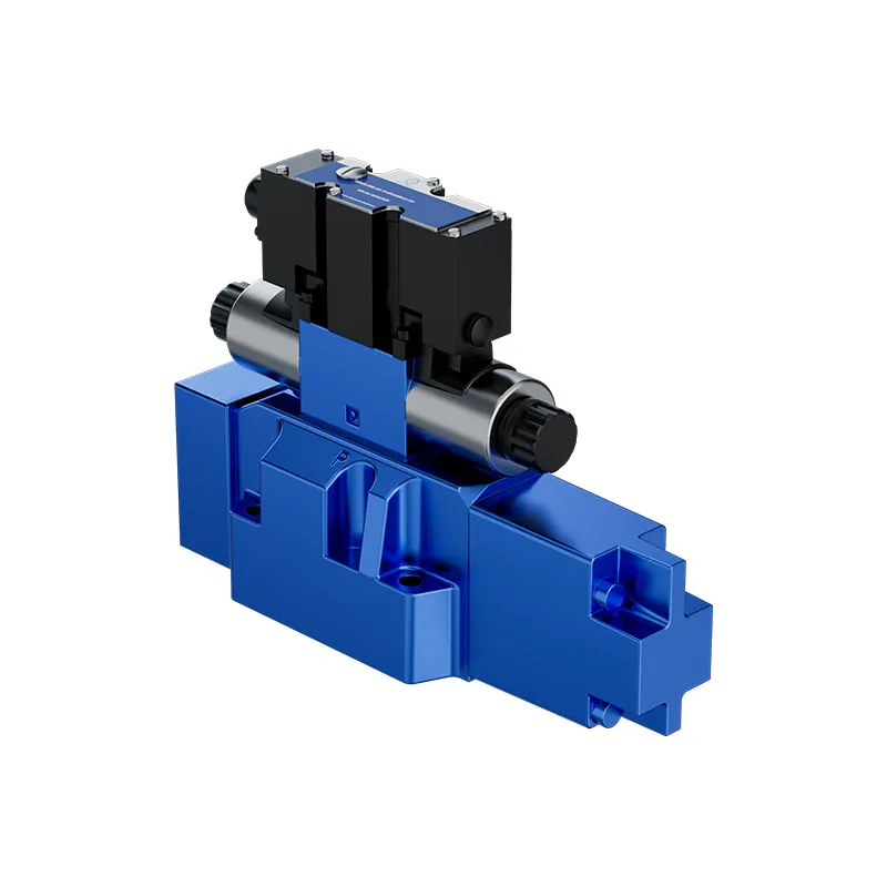
Prance lists pilot-operated proportional directional valves, including the 4WRLE family. Such a directional stage belongs to the broader discussion of controlling hydraulic flow. The original product photographs here identify that related family; they do not show a slip-in logic poppet or prove a particular pilot ratio, cover arrangement or interchange.
If a directional stage is proposed within a logic-valve control circuit, its complete configuration must suit the pilot-flow demand, pressure, return conditions and required state. The same principle applies to a replacement pilot valve: an exterior resemblance cannot establish the internal center condition or drain arrangement.
Send the original main-stage and cover codes, schematic, operating sequence, oil conditions and available pressure traces with the inquiry. Ask for confirmation of the complete assembly rather than a loose ratio value. This keeps the purchasing discussion connected to the function the machine must perform.

Verify the result without turning diagnosis into an unsafe trial
Before disturbing the assembly, isolate the machine and control hazardous energy under its approved procedure. Accumulators, suspended loads and trapped chambers can retain energy after pump shutdown. Do not loosen a cover, plug or pressure connection to discover whether a chamber is pressurized.
After an authorized repair, the acceptance sequence should distinguish command, pilot pressure, main-flow response and actuator behavior. Start under the manufacturer’s controlled commissioning conditions, then compare the relevant duty states. A satisfactory unloaded movement alone does not prove that the same force margin exists with return pressure or load applied.
Record the confirmed configuration and the measured state that distinguishes success from failure. If the valve switches in the wrong direction, hunts or produces unexpected motion, stop and revisit the signed balance and routing. Repeated cycling is not a substitute for a correct schematic.
Foire aux questions
Is a larger pilot ratio always better?
No. A ratio changes how particular pressures influence the force balance, and its meaning depends on the named areas. The required function, pressure variations and dynamic behavior determine suitability. Compare complete configurations rather than selecting the largest number.
Can I divide load pressure by the catalog ratio?
Only when the manufacturer’s equation for that exact function permits it and the other forces and pressures are accounted for. The simplified pilot-to-close example above includes two main-port pressures and a spring; a single division omits those terms.
Why can backpressure change the opening condition?
Backpressure acts on whichever effective areas are connected to that port or chamber. It may assist opening or closing depending on the geometry and routing. Identify the pressure exposure before deciding its sign.
Does a matching slip-in cavity prove interchangeability?
It establishes only part of the mechanical interface. Area definitions, springs, cover functions, pilot restrictions, pressure limits and flow behavior still need comparison. Use the complete approved assembly documentation.
Does the pictured 4WRLE identify the logic element?
No. It is an original photograph of a related pilot-operated proportional directional-valve family. A logic cartridge and its area ratio require their own drawing, code and functional evidence.
Ressources produits et d'ingénierie associées
Valve proportionnelle pilotée hydraulique 4WRLE, gamme de produits de vannes hydrauliques, Vanne à commande directe hydraulique : Utilisations et avantages, Classement du débit de la vanne hydraulique : Lire correctement les courbes de chute de pression. Confirmer le code complet du produit et les exigences d'application lors de la demande d'une revue de configuration.
Références techniques
- Maplesoft cartridge valve model: defined pilot areas and pressure balance
- Kitagawa, Sanada and Wu: proportional flow control using a PWM-controlled logic valve
- OpenStax: pressure force and hydraulic area
Further learning: hydraulic valves
mod-12 lec-12 General Control Valve Analysis by nptelhrd provides background on valve functions. The NPTEL lesson explains directional-valve metering and flow paths; it does not certify a particular cartridge, damping option or interchange. It supplements the component fundamentals; it is not a test procedure for the complete circuit discussed above.